180 Keysight EXG and MXG X-Series Signal Generators User’s Guide
Basic Digital Operation for N5172B/82B with Options 653/655/656/657
Using Waveform Markers
Using the RF Blanking Marker Function
While you can set a marker function (described as Marker Routing on the softkey label in the
Marker Utilities menu) either before or after setting the marker points (page 176), setting a marker
function before you set marker points may change the RF output. RF Blanking includes ALC hold
(described on page 171, note Caution regarding unleveled power). The signal generator blanks the
RF output when the marker signal goes low. This example is a continuation of the previous example,
Viewing a Marker Pulse.
1. Using the factory–supplied segment SINE_TEST_WFM, set Marker 1 across points 1−180
(page 176).
2. From the Marker Routing softkey menu, assign RF Blanking to Marker 1:
In the second Arb menu (page 174), press Marker Utilities > Marker Routing > Pulse/RF
Blank > Marker 1.
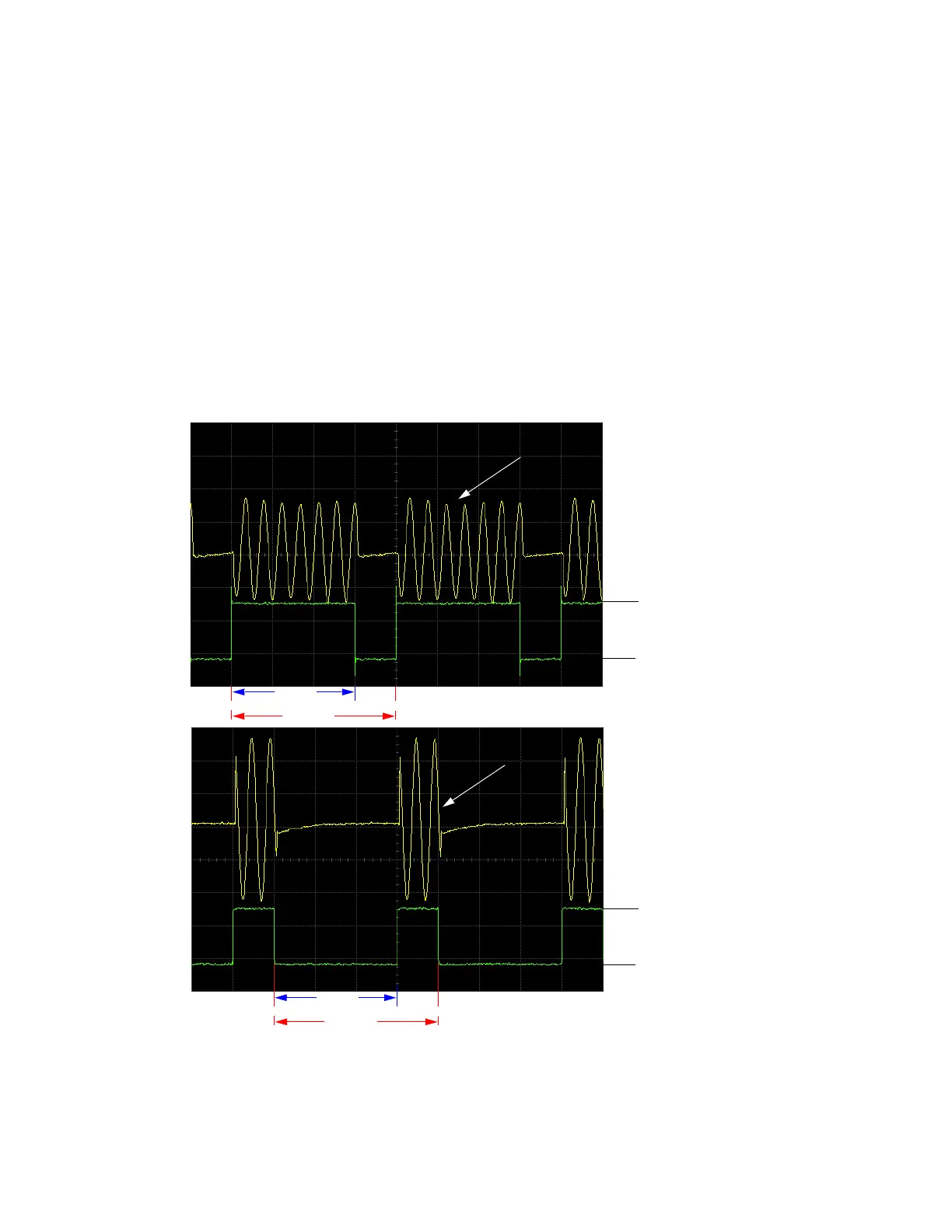
Marker Polarity = Positive
When marker polarity is positive (the default
setting), the RF output is blanked during the off
marker points.
200
180
Point 1
Marker
Segment
RF Signal
200180
Point 1
Marker
Segment
Marker Polarity = Negative
When marker polarity is negative, the
RF output is blanked during the on marker
points
≈3.3V
0V
≈3.3V
0V
RF Signal
RF Signal
RF Signal