Home
Keysight Technologies
Measuring Instruments
X Series
Keysight Technologies X Series User Manual
4
of 1
of 1 rating
502 pages
Give review
Manual
Specs
To Next Page
To Next Page
To Previous Page
To Previous Page
Loading...
Keysi
ght E
XG and M
XG X-Ser
ies Si
gnal G
enera
tors Us
er’s G
uide
45
Setting Pr
eferences & Enabling Options for All Models
How to Set Remot
e Operation Pr
efer
enc
es
Configuring Remot
e Langua
ges
Figur
e
2-2
N5171B/72B/81
B/82B
Utility
>
I/O Conf
ig
For details on
each key
, use key help
as described on
page
56
.
Select the desired
Remote language.
Refer to the
SCPI
Command Reference
.
62
64
Table of Contents
Default Chapter
5
Table of Contents
5
Models, Options, and Front/Rear Panels for All Models
19
Models of EXG and MXG X-Series Signal Generators
20
RF Analog Models
20
RF Vector Models
20
Microwave Analog Models
20
N5171B/N5181B RF Analog Signal Generators, Options and Features
21
Analog Modulation
21
General Performance Features
22
N5172B/N5182B RF Vector Signal Generators, Options and Features
24
Analog Modulation
24
General Performance Features
25
Vector Features
26
Vector Firmware Applications
29
N5173B/N5183B Microwave Analog Signal Generators, Options and Features
31
Analog Modulation
31
General Performance Features
33
Front Panel Overview
34
Host USB
34
Display
34
Softkeys
34
Numeric Keypad
34
Arrows and Select
35
Page up
35
Menus
35
Trigger
35
Local Cancel/(Esc)
35
10. Help
35
11. Preset and User Preset
36
RF Output (N5171B, N5172B, N5181B, N5182B)
36
RF Output (N5173B, N5183B)
36
13. RF On/Off and LED
36
14. Mod On/Off and LED
36
15. Page down
36
I Input (N5172B/82B RF Vector Models Only)
37
Q Input (N5172B/82B RF Vector Models Only)
37
18. Knob
37
19. Incr Set
37
20. Return
37
21. more and LED
37
22. Power Switch and Leds
37
Front Panel Display
38
Active Function Area
38
Frequency Area
38
Annunciators
38
Amplitude Area
40
Error Message Area
40
Text Area
40
Softkey Label Area
40
Contents
40
Rear Panel Overview (N5171B, N5172B, N5181B, & N5182B)
41
AC Power Receptacle
41
Ext 1 & Ext 2
42
Lf out
42
Sweep out
42
Pulse
42
Trig 1 & 2
42
Ref in
42
8. 10 Mhz out
43
Gpib
43
10. Lan
43
11. Device USB
43
12. Host USB
43
13. SD Card
43
Digital Modulation Connectors (N5172B/82B RF Vector Models Only)
44
I Out, Q Out, Out, out
44
Bb Trig 1 & Bb Trig 2
44
Event 1
44
Pat Trig
45
Digital Bus I/O
45
AUX I/O Connector
46
Rear Panel Overview (N5173B & N5183B)
50
AC Power Receptacle
50
Ext 1 & Ext 2
51
Lf out
51
Sweep out
51
Pulse
51
Trig 1 & 2
51
Ref in
51
8. 10 Mhz out
52
Gpib
52
10. Lan
52
11. Device USB
52
12. Host USB
52
13. SD Card
52
14. Alc Input
52
15. Z Axis Output
53
Setting Preferences & Enabling Options for All Models
55
How to Set User Preferences
56
Display Settings
57
Power on and Preset
58
Front Panel Knob Resolution
58
Setting Time and Date
59
Reference Oscillator Tune
60
How to Upgrade Firmware
61
How to Set Remote Operation Preferences
61
GPIB Address and Remote Language
61
Configuring the LAN Interface
62
Enabling LAN Services: "Browser," "Sockets," and "VXI-11
62
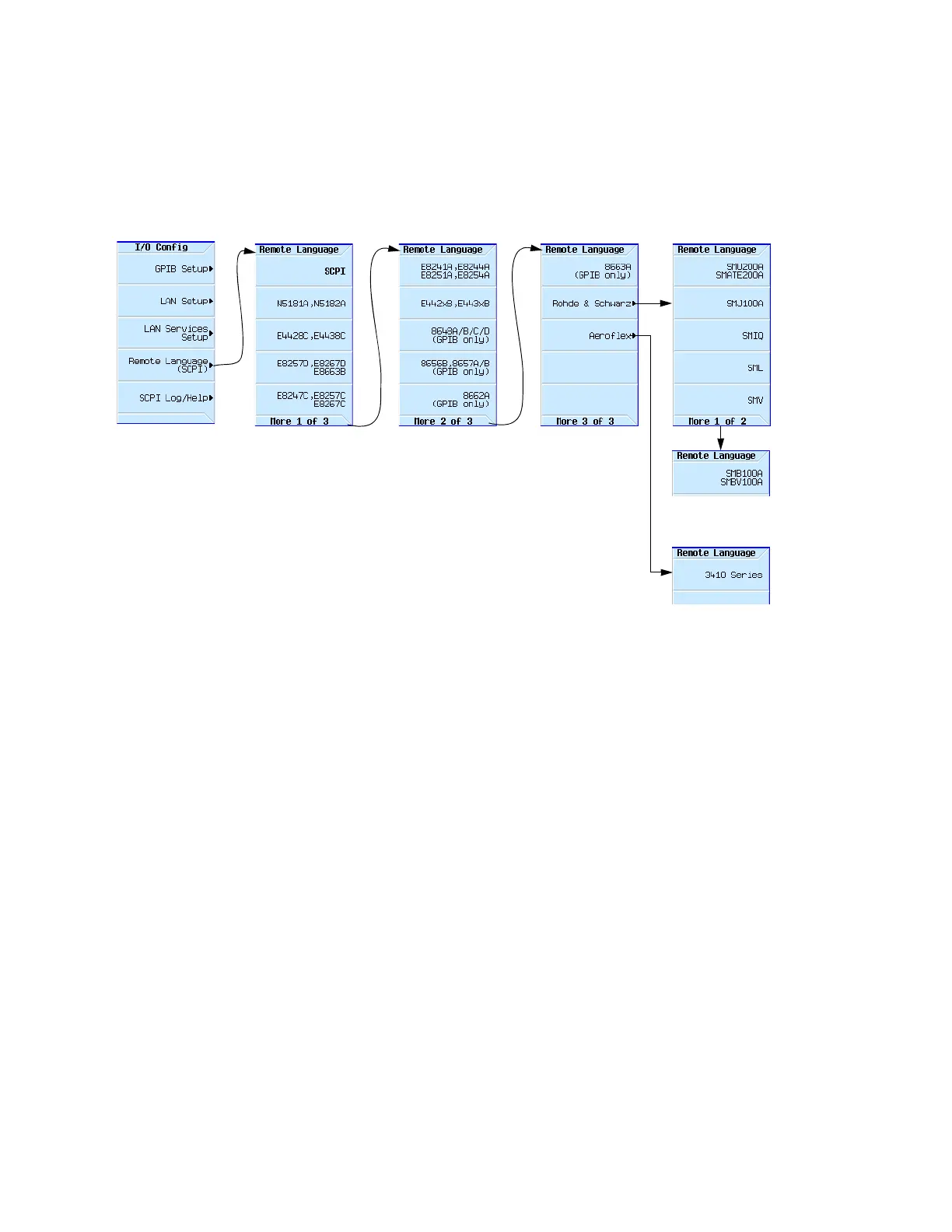
Configuring Remote Languages
63
Configuring Preset Languages
65
How to Enable an Option
67
Viewing Options and Licenses
67
Hardware Assembly Installation and Removal Softkeys
68
Modes of Operation for All Models
69
Modes of Operation
70
Continuous Wave (CW) Mode
70
Swept Signal Mode
70
Analog Modulation Mode (AM, FM, ΦM, and Pulse)
70
Digital Modulation Mode (N5172B/82B RF Vector Models W/ Option 65X Only)
71
Front Panel Operation for All Models
73
Returning to a Known State with the Preset Key
74
Viewing Key Descriptions with the Help Key
74
Entering/Editing Numbers and Text with Number and Arrow Keys
75
Entering Numbers and Moving the Cursor
75
Entering Alpha Characters
75
Example: Using a Table Editor
76
Setting Frequency and Amplitude with FREQ and AMPTD Keys
77
Example: Configuring a 700 Mhz, −20 Dbm Continuous Wave Output
78
Using an External Reference Oscillator
78
Setting ALC Bandwidth Control with Amplitude Softkeys
79
Using Swept Signal Mode (Configuring a Swept Output)
80
Routing Signals
81
Step Sweep
81
List Sweep
83
Example: Using a Single Sweep
86
Example: Manual Control of Sweep
87
Using Analog Modulation on the RF Carrier Signal (Option UNT)
88
Example
88
Simultaneous Modulation
89
Working with Files (Viewing/Storing/Loading/Moving)
90
File Softkeys
91
Viewing a List of Stored Files
92
Storing a File
94
Loading (Recalling) a Stored File
95
Moving a File from One Media to Another
96
Working with Instrument State Files
96
Selecting the Default Storage Media
101
Contents
102
Reading Error Messages
102
Error Message Format
102
Optimizing Performance for All Models
103
Using the Dual Power Meter Display (with USB U2000A Series Power Sensors)
104
Example: Dual Power Meter Calibration
106
Using the USB Pass through Commands
111
Procedure
111
Using the Power Meter Servo
113
Power Meter Servo Configuration
114
Example
115
Using Flatness Correction
116
Creating a User Flatness Correction Array
118
Power Meter
119
Recalling and Applying a User Flatness Correction Array
124
Using Internal Channel Correction (N5172B/82B Only)
125
Configure Internal Channel Correction
128
Perform Enhanced Factory Calibration
128
Using I/Q Mod Skew Cal
129
Using External Leveling (N5173B/83B Only)
132
Option 1E1 Output Attenuator Behavior and Use
135
Configure External Leveling
135
Using Unleveled Operating Modes
139
ALC off Mode
139
Power Search Mode
140
Using an Output Offset, Reference, or Multiplier
143
Setting an Output Offset
143
Setting an Output Reference
144
Setting a Frequency Multiplier
145
Using the Frequency and Phase Reference Softkeys
146
Using Free Run, Step Dwell, and Timer Trigger
147
Understanding Free Run, Step Dwell, and Timer Trigger Setup
147
Using Filters (N5162A and N5182A Only)
148
Dual ARB Modulation Filter Types
149
Arb Custom Modulation Filter Types
151
Creating Real Filters with Arb Custom Modulation
151
Using a USB Keyboard
152
N5171B/72B/73B EXG and N5181B/82B/83B MXG
153
And Familiarize
153
Using Pulse Modulation for All Models with Options UNU, UNW
153
Pulse Characteristics
155
The Basic Procedure
157
Example
158
Pulse Train (Option 320 - Requires: Option UNW)
159
Basic Digital Operation for N5172B/82B-No BBG Option Installed
165
I/Q Modulation
166
Configuring the Front Panel Inputs
167
Basic Digital Operation for N5172B/82B with Options
169
Waveform Files (Segments and Sequences)
171
Signal Generator Memory (Volatile and Non-Volatile)
171
Using Dual ARB Softkeys
172
Storing, Loading, and Playing a Waveform Segment
173
Loading a Waveform Segment into BBG Media
173
Storing/Renaming a Waveform Segment to Internal Media or USB Media
174
Playing a Waveform Segment
174
Waveform Sequence Softkeys
176
Creating a Waveform Sequence
177
Viewing the Contents of a Waveform Sequence
178
Editing a Waveform Sequence
178
Playing a Waveform Sequence
179
Saving a Waveform's Settings & Parameters
181
Viewing and Modifying File Header Information
183
Viewing & Editing a File Header Without Selecting the Waveform
185
Using Waveform Markers
187
Waveform Marker Concepts
188
Accessing Marker Utilities
192
Viewing Waveform Segment Markers
193
Clearing Marker Points from a Waveform Segment
193
Setting Marker Points in a Waveform Segment
194
Viewing a Marker Pulse
196
Using the RF Blanking Marker Function
198
Setting Marker Polarity
199
Controlling Markers in a Waveform Sequence
199
Using the EVENT Output Signal as an Instrument Trigger
202
Triggering a Waveform
203
Trigger Type
204
Trigger Source
205
Example: Segment Advance Triggering
206
Example: Gated Triggering
207
Example: External Triggering
209
Clipping a Waveform
210
How Power Peaks Develop
211
How Power Peaks Cause Spectral Regrowth
213
How Clipping Reduces Peak-To-Average Power and Spectral Regrowth
214
Configuring Circular Clipping
217
Configuring Rectangular Clipping
218
Scaling a Waveform
219
How DAC Over-Range Errors Occur
220
How Scaling Eliminates DAC Over-Range Errors
221
Setting Waveform Runtime Scaling
222
Setting Waveform Scaling
223
Setting the Baseband Frequency Offset
225
DAC Over-Range Conditions and Scaling
227
Contents
227
Using I/Q Modulation
229
Using the Rear Panel I and Q Output Connectors
230
Configuring the Front Panel I and Q Input Connectors
231
I/Q Adjustments
232
I/Q Calibration
233
Using the Equalization Filter
235
Using Finite Impulse Response (FIR) Filters in the Dual ARB Real-Time Modulation Filter
237
Creating a User-Defined FIR Filter Using the FIR Table Editor
238
Modifying a FIR Filter Using the FIR Table Editor
243
Loading the Default Gaussian FIR File
243
Modifying the Coefficients
244
Storing the Filter to Memory
245
Using the Custom Real-Time I/Q Baseband Generator
247
Selecting Predefined Custom Modulation Modes
247
Creating User-Defined Custom Modulation
248
Setting the Real-Time Modulation Filter
250
Multiple Baseband Generator Synchronization
252
Understanding the Master/Slave System
254
Equipment Setup
255
Configuring the Setup
255
Making Changes to the Multiple Synchronization Setup and Resynchronizing the Master/Slave System
258
Configuring the Option 012 (lo In/Out for Phase Coherency) with MIMO
259
Using Real-Time Applications Softkeys
263
Waveform Licensing
264
Understanding Waveform Licensing
264
Installing an Option N5182-22X or Option N5182B-25X
264
Licensing a Signal Generator Waveform
264
Using Custom Digital Modulation for N5172B/82B with Option 431 and
273
Using ARB Custom Modulation Softkeys
274
ARB Custom Modulation Mode
275
Real-Time Custom Modulation Mode
275
Creating and Using Bit Files
283
Creating a User File
284
Renaming and Saving a User File
285
Recalling a User File
286
Modifying an Existing User File
286
Applying Bit Errors to a User File
287
Using Customized Burst Shape Curves
288
Understanding Burst Shape
288
Creating a User-Defined Burst Shape Curve
290
Storing a User-Defined Burst Shape Curve
292
Recalling a User-Defined Burst Shape Curve
292
Using the Arbitrary Waveform Generator
294
Using Predefined Custom Digital Modulation
294
Creating a Custom Digital Modulation State
295
Storing a Custom Digital Modulation State
297
Recalling a Custom Digital Modulation State
298
Defining a Modulation
299
Creating a Custom Multicarrier Digital Modulation State
306
Storing a Custom Multicarrier Digital Modulation State
308
Applying Changes to an Active Multicarrier Digital Modulation State
308
Using Finite Impulse Response (FIR) Filters with Custom Modulation
310
Understanding FIR Filters
310
Creating a User-Defined FIR Filter Using the FIR Table Editor
312
Modifying a FIR Filter Using the FIR Table Editor
317
Loading the Default Gaussian FIR File
317
Modifying the Coefficients
318
Storing the Filter to Memory
319
Using the Custom Real-Time I/Q Baseband Generator
320
To Select Custom Real-Time I/Q Base Band Predefined Modes
320
Creating User-Defined Custom Modulation
321
Differential Encoding
323
Using Differential Encoding
326
Using Multitone and Two-Tone Waveforms for N5172B/82B with Option 430 and
329
Creating a Custom Multitone Waveform
329
Using Multitone Softkeys
330
Multitone Softkeys
330
Initializing the Multitone Setup Table Editor
330
Configuring Tone Powers and Tone Phases
331
Removing a Tone
331
Generating the Waveform
331
Configuring the RF Output
331
Applying Changes to an Active Multitone Signal
332
Creating a Custom Two-Tone Waveform
334
Using Two-Tone Softkeys
335
Two-Tone Softkeys
335
Creating a Two-Tone Waveform
336
Viewing a Two-Tone Waveform
336
Minimizing Carrier Feedthrough
337
Changing the Alignment of a Two-Tone Waveform
338
Adding Real-Time Noise to a Signal for N5172B/82B with Option 403 and
341
Adding Real-Time Noise (AWGN) to a Dual ARB Waveform
342
Eb/No Adjustment Softkeys for Real Time I/Q Baseband AWGN
345
Using Real-Time AWGN Softkeys
348
Contents
349
Using Real-Time Phase Noise Impairments for N5172B/82B with Option 432 and
349
Using Real-Time Phase Noise Impairment Softkeys
350
Phase Noise Shape and Additive Phase Noise Impairments
351
Understanding the Phase Noise Adjustments
353
DAC Over-Range Conditions and Scaling
354
Using Real-Time Fading for N5172B/82B with Option 660 and
355
Using Real-Time Fading Softkeys
356
To Configure a Real-Time Fading Simulation
357
Using vor [VHF Omnidirectional Range] Softkeys
360
Using Avionics VOR/ILS Softkeys for N5171B/72B and N5181B/82B with Option
360
To Set the vor Mode that Produces a Full or Partial vor Signal
363
To Set the vor Carrier Frequency
363
To Set the vor Bearing Angle between the VAR Signal and the REF Signal
365
To Set the vor Bearing Direction as from or to
366
To Set the Frequency of the Reference Signal (REF Freq) and the Variable Phase Signal (VAR Freq)
366
To Set the Amount of FM Deviation that the 30 Hz Reference Signal (REF Freq) Applies on the Sub-Carrier
367
To Set the am Depth of the Variable Phase Signal (VAR Freq)
367
To Set the Frequency of the Sub-Carrier Signal (Subcarrier Freq)
368
To Set the Sub-Carrier am Depth that Modulates the vor Carrier
368
To Set or Return the vor Subsystem Parameters to a Default State
369
Example of Setting All vor Parameters
370
Using COM/ID Softkeys
372
To Set the COM/ID on or off
373
To Set the COM/ID Type between Code or Tone
373
To Set the COM/ID 3-Character Code (Airport Identification Code)
373
To Set the COM/ID Tone/Code Modulating Frequency
374
To Set the COM/ID Tone am Depth
374
To Set or Return the COM/ID Parameters to a Default State
375
Example of Setting All COM/ID Parameters
376
Using ILS Localizer Softkeys
378
To Set the ILS Localizer Mode to Produce a Full or Partial Signal
382
To Set the ILS Localizer Carrier Frequency
384
To Set the ILS Localizer Left Frequency
385
To Set the ILS Localizer Right Frequency
385
To Set the ILS Localizer Phase of the Right Signal Relative to the Left
386
To Set the ILS Localizer DDM Polarity to Fly Left or Fly Right
386
To Set the ILS Localizer DDM Value
388
To Set the ILS Localizer DDM Value in Micro-Amps (Ua)
388
To Set the ILS Localizer DDM Value as a Percentage (%)
389
To Set the ILS Localizer SDM Value
389
To Set or Return the ILS Localizer Parameters to a Default State
390
Example of Setting All ILS Localizer Parameters
391
Using ILS Glide Slope Softkeys
393
To Set the ILS Glide Slope Mode to Produce a Full or Partial Signal
397
To Set the ILS Glide Slope Carrier Frequency
399
To Set the ILS Glide Slope up Frequency
400
To Set the ILS Glide Slope down Frequency
400
To Set the ILS Glide Slope Phase of the down Signal Relative to the up
401
To Set the ILS Glide Slope DDM Polarity to Fly up or Fly down
401
To Set the ILS Glide Slope DDM Value
403
To Set the ILS Glide Slope DDM Value in Micro-Amps (Ua)
403
To Set the ILS Glide Slope DDM Value in Percentage (%)
404
To Set the ILS Glide Slope SDM Value
404
To Set or Return the ILS Glide Slope Parameters to a Default State
405
Example of Setting All ILS Glide Slope Parameters
406
Using ILS Marker Beacon Softkeys
408
To Set the ILS Marker Beacon Mode to Off, Inner, Middle, or Outer
410
To Set the ILS Marker Beacon Carrier Frequency
410
To Set the ILS Marker Beacon am Depth
411
To Set the ILS Marker Beacon Inner Marker Frequency
411
To Set the ILS Marker Beacon Middle Marker Frequency
411
To Set the ILS Marker Beacon Outer Marker Frequency
412
To Set or Return the ILS Marker Beacon Parameters to a Default State
412
Example of Setting All ILS Marker Beacon Parameters
413
Using Baseband Operating Mode for N5172B/82B (Primary, BERT, or N5102A)
415
To Set the Baseband Operating Mode to BERT
416
To Set the Baseband Operating Mode to N5102A
417
To Set the Baseband Operating Mode to Primary
418
16 Using BERT for N5172B/82B with Option UN7
419
Bit Error Rate Test
420
Block Diagram
420
Clock Gate Function
420
Clock/Gate Delay Function
421
Clock Delay Function
423
Gate Delay Function in the Clock Mode
424
Triggering
425
Data Processing
427
Repeat Measurements
428
Testing Signal Definitions
429
Verifying BERT Operation
430
BERT Measurement Setup Using Self-Test Mode
432
Measurement Example Using Custom Digital Modulation
434
(Requires Option 431)
434
Using the N5102A Digital Signal Interface Module for N5172B/82B with Option 003/004 and
437
Clock Timing
438
Clock and Sample Rates
438
Clock Source
440
Common Frequency Reference
441
Clock Timing for Parallel Data
443
Clock Timing for Parallel Interleaved Data
445
Clock Timing for Serial Data
446
Clock Timing for Phase and Skew Adjustments
447
Contents
443
Connecting the Clock Source and the Device under Test
449
Data Types
451
Output Mode
451
Input Mode
451
Operating the N5102A Module in Output Mode
452
Setting up the Signal Generator Baseband Data
452
Accessing the N5102A Module User Interface
452
Choosing the Logic Type and Port Configuration
453
Selecting the Output Direction
454
Selecting the Data Parameters
454
Configuring the Clock Signal
457
Generating Digital Data
461
Operating the N5102A Module in Input Mode
462
Accessing the N5102A Module User Interface
462
Selecting the Input Direction
463
Choosing the Logic Type and Port Configuration
463
Configuring the Clock Signal
464
Selecting the Data Parameters
468
Digital Data
470
18 Troubleshooting
471
Display
472
The Display Is too Dark to Read
472
The Display Turns Black When Using USB Media
472
Signal Generator Lock-Up
472
RF Output
473
No RF Output
473
Power Supply Shuts down
473
No Modulation at the RF Output
473
RF Output Power too Low
473
Distortion
473
Signal Loss While Working with a Spectrum Analyzer
474
Signal Loss While Working with a Mixer
475
Sweep
477
Cannot Turn off Sweep
477
Sweep Appears Stalled
477
Incorrect List Sweep Dwell Time
477
List Sweep Information Is Missing from a Recalled Register
477
Amplitude Does Not Change in List or Step Sweep
478
Internal Media Data Storage
478
Instrument State Saved but the Register Is Empty or Contains the Wrong State
478
USB Media Data Storage
478
Instrument Recognizes USB Media Connection, but Does Not Display Files
478
Preset
478
The Signal Generator Does Not Respond
478
Pressing Preset Performs a User Preset
478
Error Messages
479
Error Message Types
479
Front Panel Tests
480
Self Test Overview
480
Licenses
482
A Time-Based License Quits Working
482
Cannot Load a Time-Based License
482
Contacting Keysight Technologies
483
Returning a Signal Generator to Keysight
483
19 Working in a Secure Environment
485
How to Obtain the Security Features Document
485
Using Secure Display
486
Other manuals for Keysight Technologies X Series
Service Guide
671 pages
Programming Guide
398 pages
Security Features And Document Of Volatility
58 pages
Installation Note
10 pages
Manual
56 pages
Installation Notes
27 pages
4
Based on 1 rating
Ask a question
Give review
Questions and Answers:
Need help?
Do you have a question about the Keysight Technologies X Series and is the answer not in the manual?
Ask a question
Keysight Technologies X Series Specifications
General
Brand
Keysight Technologies
Model
X Series
Category
Measuring Instruments
Language
English
Related product manuals
MSO-X 2022A
352 pages
DSO-X 2012A
352 pages
DSO-X 2014A
352 pages
DSO-X 2022A
352 pages
InfiniiVision MSO-X 4022A
1762 pages
InfiniiVision MSO-X 3034A
432 pages
InfiniiVision MSO-X 3014A
432 pages
InfiniiVision MSO-X 3024A
432 pages
InfiniiVision 6000 X Series
130 pages
InfiniiVision 3000 X Series
432 pages
InfiniiVision 2000 X Series
378 pages
InfiniiVision 4000 X Series
1762 pages