Keysight EXG and MXG X-Series Signal Generators User’s Guide 431
Using the N5102A Digital Signal Interface Module for N5172B/82B with Option 003/004 and
653/655/656/657
Connecting the Clock Source and the Device Under Test
Connecting the Clock Source and the Device Under Test
As shown in Figure 17-3 on page 424, there are numerous ways to provide a common frequency
reference to the system components (signal generator, N5102A module, and the device under test).
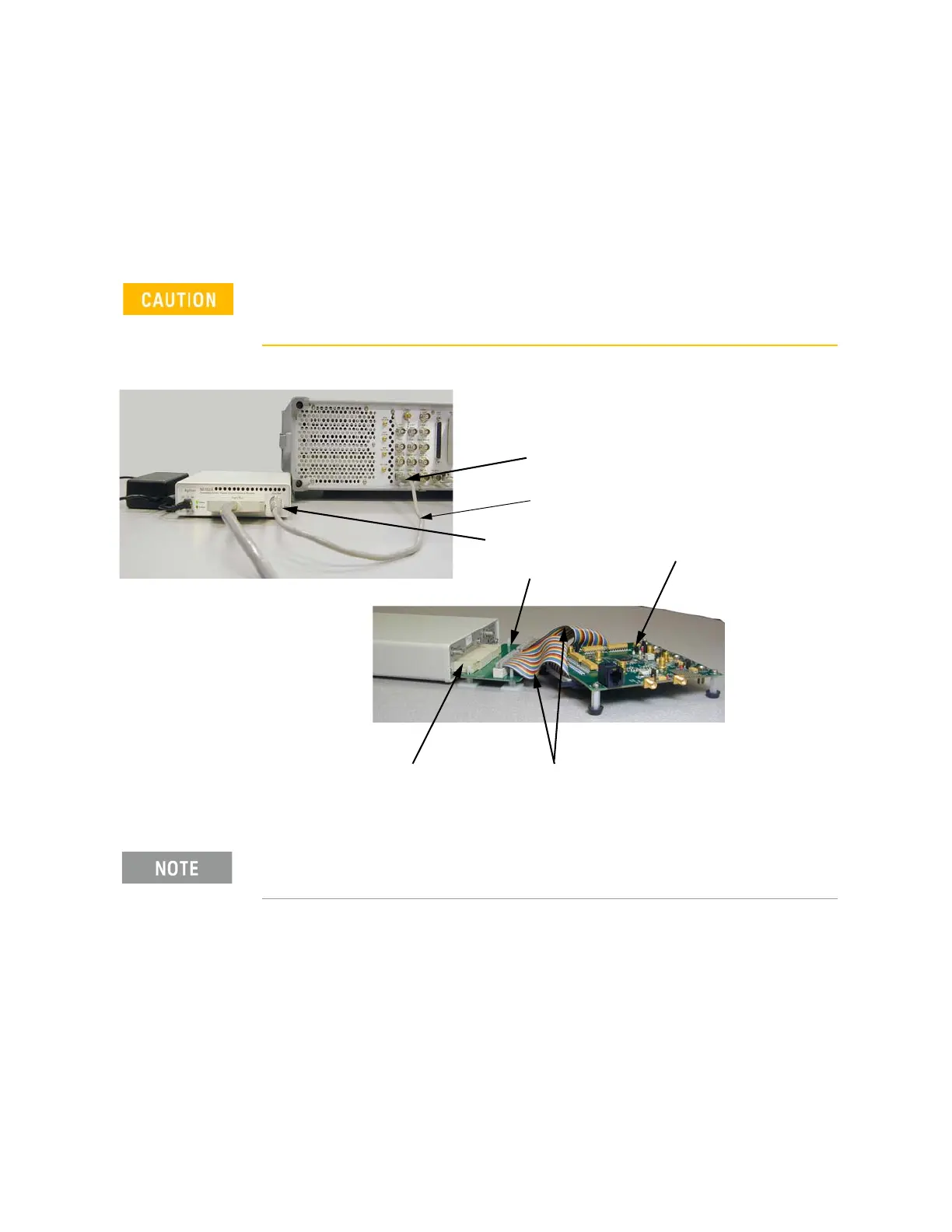
Figure 17-8 shows an example setup where the signal generator supplies the common frequency
reference and the N5102A module is providing the clock to the device.
Figure 17-8 Example Setup using the Signal Generator 10 MHz Frequency Reference
1. Refer to the five setup diagrams in Figure 17-3 on page 424 and connect the frequency
reference cable according to the clock source.
2. If an external clock source is used, connect the external clock signal to the Ext Clock In
connector on the interface module.
The Device Interface connector on the interface module communicates
using high speed digital data. Use ESD precautions to eliminate potential
damage when making connections.
You must disconnect the digital bus cable and the digital module while
downloading firmware to the signal generator.
Signal generator 10 MHz Out
Freq Ref connector
Device interface connection
Device under test
Break-out board
User furnished ribbon cable(s) connect
between the device and break-out board.
Common Freq Ref cable
The clock to the device is in the ribbon
cable.