202 Keysight EXG and MXG X-Series Signal Generators User’s Guide
Basic Digital Operation for N5172B/82B with Options 653/655/656/657
Scaling a Waveform
How DAC Over–Range Errors Occur
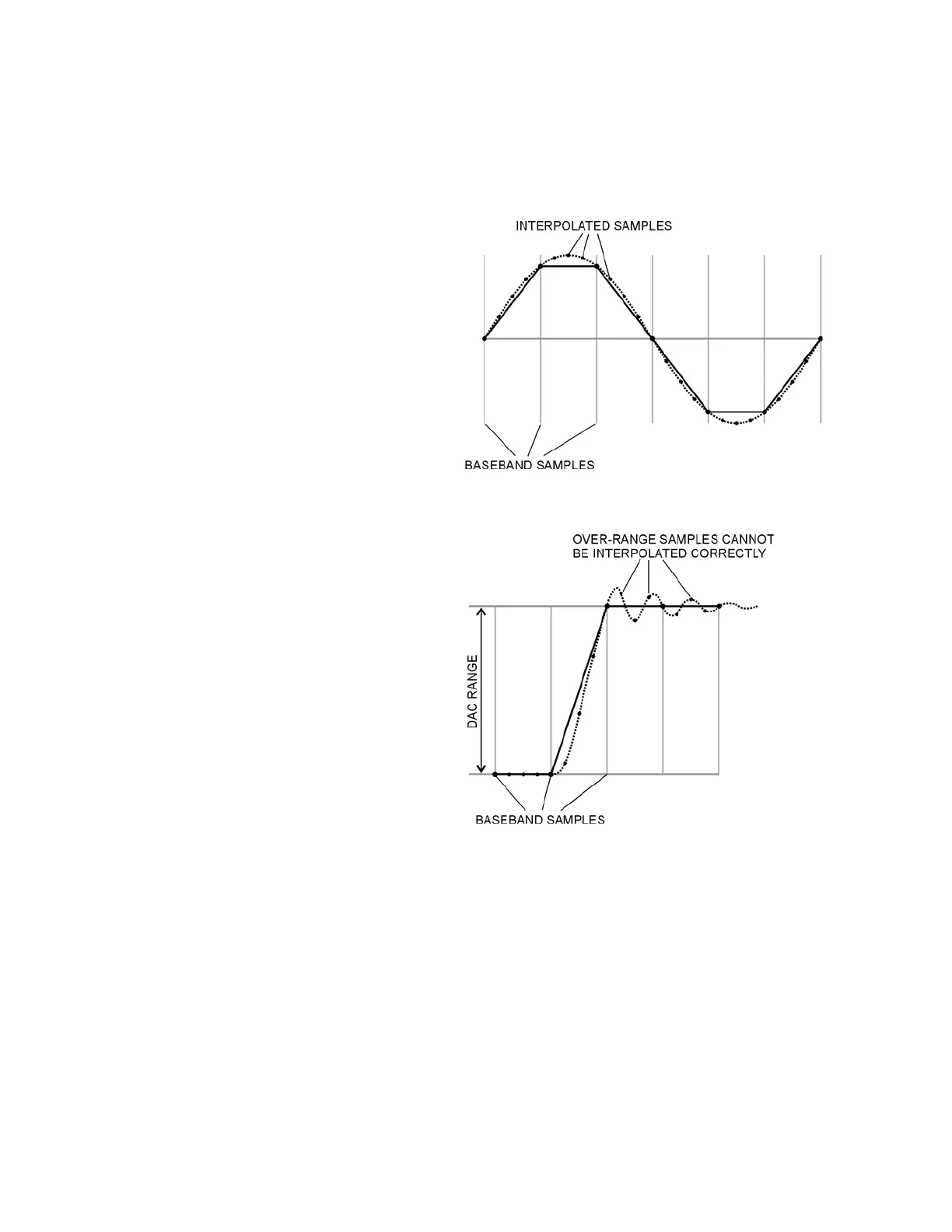
The signal generator uses an interpolator
filter when it converts digital I and Q
baseband waveforms to analog
waveforms. Because the clock rate of the
interpolator is four times that of the
baseband clock, the interpolator
calculates sample points between the
incoming baseband samples and smooths
the waveform as shown in the figure at
the right.
The interpolation filters in the DACs
overshoot the baseband waveform. If a
baseband waveform has a fast–rising
edge, the interpolator filter’s overshoot
becomes a component of the interpolated
baseband waveform. This response
causes a ripple or ringing effect at the
peak of the rising edge. If this ripple
overshoots the upper limit of the DAC
range, the interpolator calculates
erroneous sample points and is unable to
replicate the true form of the ripple (see
the figure at the right). As a result, the
signal generator reports a DAC over–
range error.