Keysight EXG and MXG X-Series Signal Generators User’s Guide 411
Using BERT for N5172B/82B with Option UN7
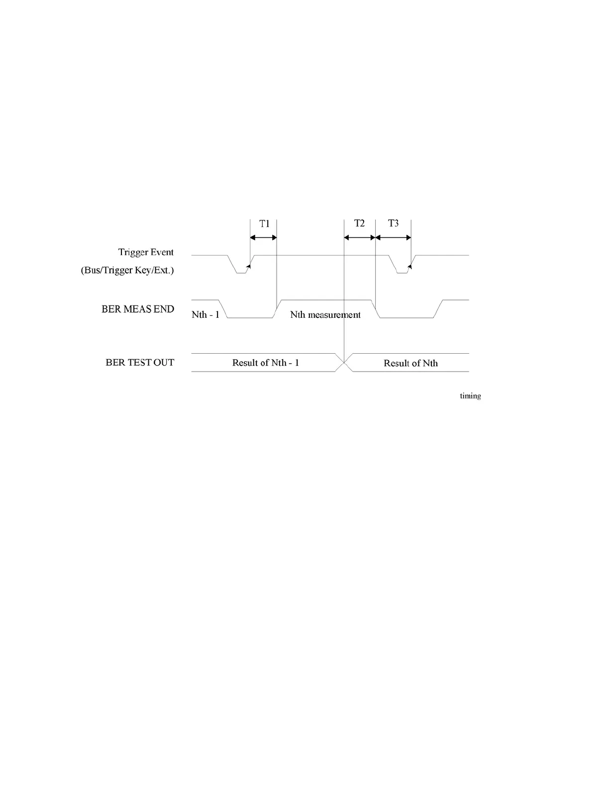
Bit Error Rate Test
Testing Signal Definitions
The timing diagram <Keysight Red >Figure 16-13, “Testing Signal Definitions,” shows the
relationships between a trigger event and the output signals at the BER MEAS END and BER TEST
OUT connectors.
If a BER MEAS END signal stays high following a trigger event, the BERT measurement is in
progress and other trigger events are ignored. This state is stored in the status register and can be
queried.
Figure 16-13 Testing Signal Definitions
— T1 is a firmware handling time measured from a Trigger event to the rising edge of a BER MEAS
END signal.
— T2 is a firmware handling time measured from the falling edge of a BER TEST OUT signal to the
falling edge of the BER MEAS END signal.
— T3 is a minimum requirement time measured from the falling edge of the BER MEAS END signal
to the next trigger event. T3 should be greater than 0 second.
The pulse output of the BER TEST OUT for the Nth-1 test result ends prior to the falling edge of the
BER MEAS END signal for the Nth measurement; so you can use this edge to start latching the Nth
test result.