212 Keysight EXG and MXG X-Series Signal Generators User’s Guide
Basic Digital Operation for N5172B/82B with Options 653/655/656/657
Using I/Q Modulation
Using the Rear Panel I and Q Output Connectors
In addition to modulating the carrier, the signal generator also routes the internally generated I and
Q signals to the rear panel I and Q output connectors. These output signals are post DAC, so they
are in analog form. You can use these rear panel I and Q signals to:
— drive a system’s transmitter stage
— test individual analog I and Q components such as an I/Q modulator
— route the I and Q signals into another signal generator
The factory default setting routes the internally generated I and Q signals to the I/Q modulator and
the rear panel I and Q output connectors. However to optimize (apply calibration factors) the rear
panel signals, you need to select the external I/Q output path.
Select and Play a Waveform
1. Press Mode > Dual ARB > Select Waveform.
2. Highlight the desired waveform.
3. Press Select Waveform > ARB Off On to On.
Optimize the Signal Path
1. Connect cables from the rear panel I and Q connectors to either a DUT or another signal
generator.
When you turn the ARB on, the signal generator automatically outputs the I and Q signals to
the rear panel connectors. You can use the rear panel I and Q signals as I and Q inputs to
another signal generator. The MXG/EXG has front panel connectors, I Input and Q Input, for
this purpose.
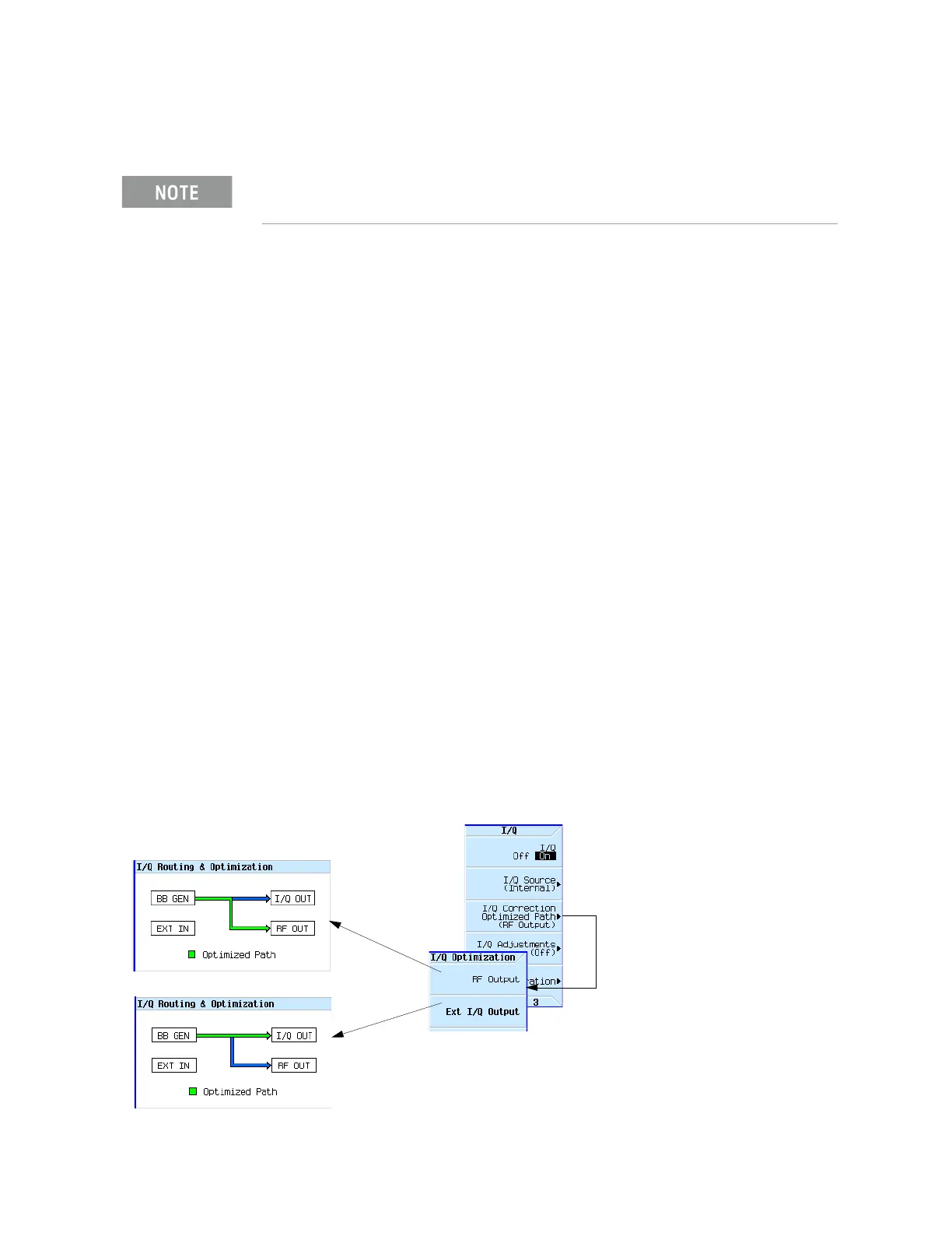
2. Press I/Q > I/Q Correction Optimized Path > Ext I/Q Output.
When you optimize a path, the path indicator turns green.
The rear panel I and Q output connectors only output a signal while using
the internal BBG.
Factory default setting—RF Output path optimized
Rear panel I/Q path optimized