402 Keysight EXG and MXG X-Series Signal Generators User’s Guide
Using BERT for N5172B/82B with Option UN7
Bit Error Rate Test
Bit Error Rate Test
The bit error rate test (BERT) capability allows you to perform bit error rate (BER) analysis on digital
communications equipment. This enables functional and parametric testing of receivers and
components including sensitivity and selectivity.
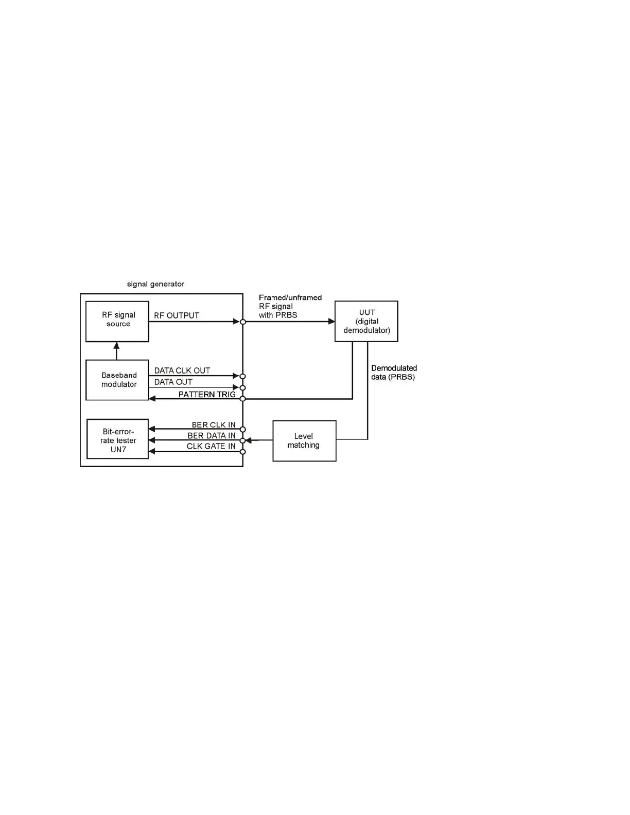
Block Diagram
When measuring BER, a clock signal that corresponds to the unit under test (UUT) output data
must be input to the BER CLK IN connector. If the clock is not available from the UUT, use the DATA
CLK OUT signal from the X-Series baseband modulator. Refer to Figure 16-16 for information
about these connections.
Figure 16-1
Clock Gate Function
When you use the clock gate function, the clock signal to the BER CLK IN (rear panel BB TRIG 1)
connector is valid only when the clock gate signal to the BER GATE IN connector is ON.
Press the Clock Gate Off On softkey to toggle the clock gate function off and on.The Clock Gate
Polarity Neg Pos softkey sets the input polarity of the clock gate signal supplied to the rear panel
BER GATE IN connector. When you select Pos (positive), the clock signal is valid when the clock
gate signal is high; when you select Neg (negative), the clock signal is valid when the clock gate
signal is low.
The following figure shows an example of the clock gate signal.