190 Keysight EXG and MXG X-Series Signal Generators User’s Guide
Basic Digital Operation for N5172B/82B with Options 653/655/656/657
Triggering a Waveform
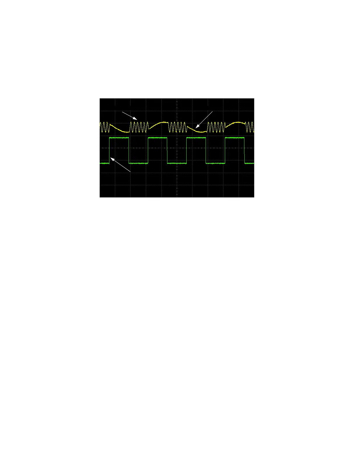
8. (Optional) Monitor the waveform:
Configure the oscilloscope to display both the output of the signal generator, and the external
triggering signal. You will see the waveform modulating the output during the gate active
periods (low in this example).
The following figure shows an example display.
RF Output
Externally Applied Gating Signal
Gate Active = Low
Modulating Waveform