Keysight B2980B User’s Guide, Edition 1 103
How to Perform Measurement
Resistance Measurement
All accessories can be used for the floating device measurement with the control
switch PULL position of the N1413A. Note that the N1425A/B and N1427A/B can
also be used for the grounded device measurement with the PUSH position.
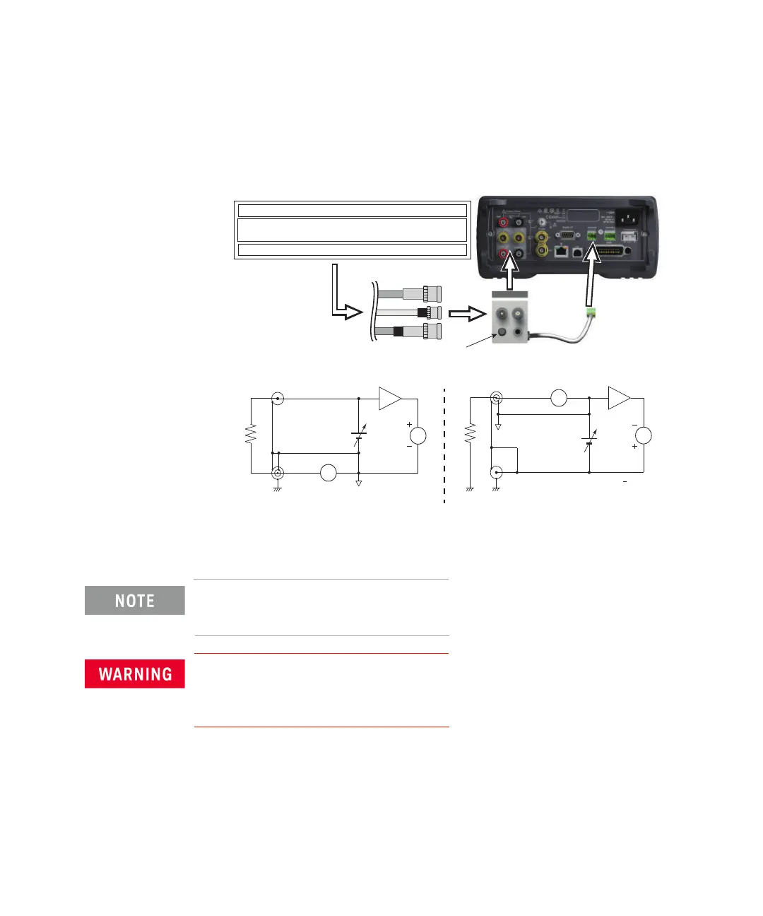
Figure 3-11 Connecting Accessory for High Resistance Measurement using N1413A
For more information about using the accessories, see Operation Manual of each
accessory.
To apply a voltage over 21V, the Interlock terminal must be connected to an
interlock circuit. See “Interlock” on page 112.
To attach the N1413A/N1414A adapter, push it to the B2985B/B2987B
connectors.
Push the adapter in firmly until it locks in-place (< 1 mm spacing)
N1413A adapter
Control switch:
PULL position for Floating device
PUSH position for Grounded device
To Interlock
PULL
PULL/PUSH
N1424A/B/C Resistivity Cell
N1425A/B Low Noise Test Lead
PULL
N1427A/B
N1428A Component Test Fixture
Triaxial
A
V
HV coaxial
V
S
V
M
= 0.01*V
S
V
M
A
V
V
S
V
M
= 0.01*V
S
V
M
Triaxial
HV coaxial
Switch PULL position for Floating device Switch PUSH position for Grounded device
100:1
100:1
Common
Common
Voltage Source Low Terminal State: FLOATING
DUT
 Loading...