TOS3200
183
Four Principal Tests for Evaluating the Safety of Electrical and Electronic Products
Appx
Earth Continuity Test
This test verifies the integrity (continuity) of the protective bonding of the equipment (Class I
equipment) designed to secure safety through the basic insulation and protective earthing. It
is also called earth (ground) bonding test.
In this test, a current in the range of 10 A to 60 A is applied for 60 seconds to few minutes.
The resistance is measured by measuring the voltage. The test current is determined by the
rating of the distribution system (such as 1.5 or 2 times the distribution system). Many stan-
dards define the resistance limit to less than or equal to 0.1 Ω (some standards define the
limit by the voltage drop) and the open-circuit voltage (no-load voltage) to less than or equal
to 6 V or 12 V.
If the continuity of the protective bonding is confirmed, we can conclude that the equipment
has the requirements for preventing electric shock even if the insulation between the primary
circuit and the accessible conductive section fails and a fault current flows through the distri-
bution system.
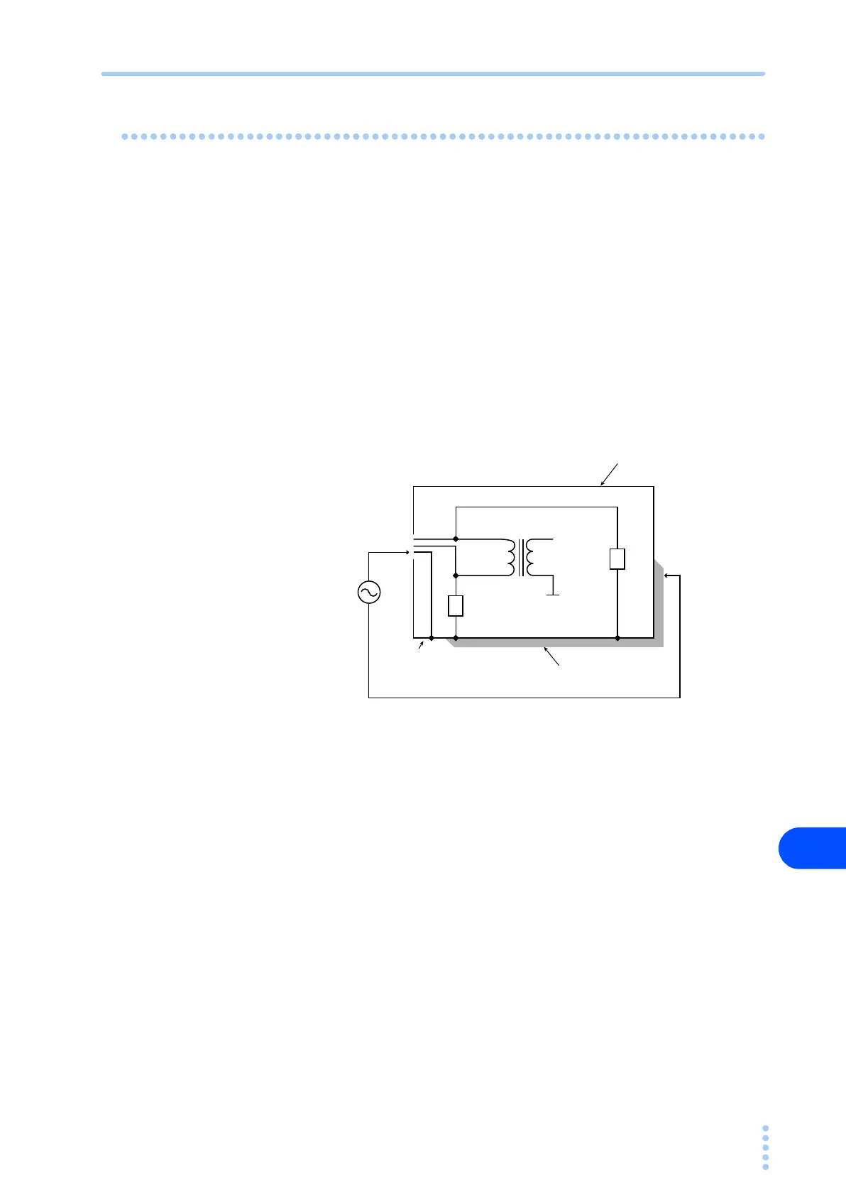
Measurement principle of the earth continuity test
Fig. B-4 Earth continuity test
N
PE
L
Z1
Z2
Enclosure
Class I Equipment
Secondary
Primary
Accessible conductive part
Protective Earth
Connect using low impedance.
Electric shock hazard if this
impedance is high
Output of the earth
continuity tester
AC 50/60 Hz
10 A to 60 A
Calculate the resistance
from the voltage and output
current between the
measurement terminals.
 Loading...


