TOS3200
59
Setting Test Conditions of the PCC Measurement
4
TC and PCC Tests
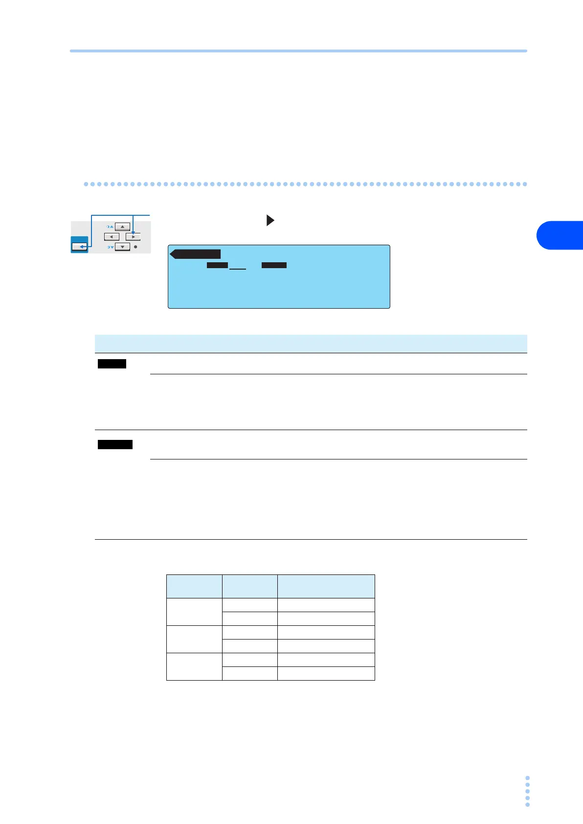
Blinking indication UP <= LOW
If the lower reference is set to a value greater than or equal to the upper reference in the
LOWER ON condition, “UP <= LOW” will blink at the upper right of the screen to indicate that
the setting is invalid.
Setup Items of PCC2/2 (MODE / RANGE)
Press the NEXT (SHIFT+ ) key to display the PCC2/2 screen.
Table 4-6 Determination of the measurement range
PCC 2 / 2
RMS AUTO
MODE RANGE
MODE RANGE
Item Description Panel operation
Selects the current measurement mode. MODE (F2) key
RMS RMS measurement
MODE
(SHIFT+F2) key
DC DC measurement
PEAK Peak measurement
Selects the measurement range.
RANGE (F3)
key
AUTO
Automatically switches the range according to the measured
value
RANGE
(SHIFT+F3) key
FIX
Fixes the range.
The measurement range is determined by the upper reference
and current measurement mode (MODE) settings. See Table 4-
6.
Measurement
range
MODE Upper reference
Range 1
DC, RMS 30 μA to 600 μA
PEAK 50 μA to 850 μA
Range 2
DC, RMS 601 μA to 6.00 mA
PEAK 851 μA to 8.50 mA
Range 3
DC, RMS 6.01 mA to 30.0 mA
PEAK 8.51 mA to 90.0 mA