52
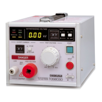
TOS3200
Setting Test Conditions of the TC Measurement
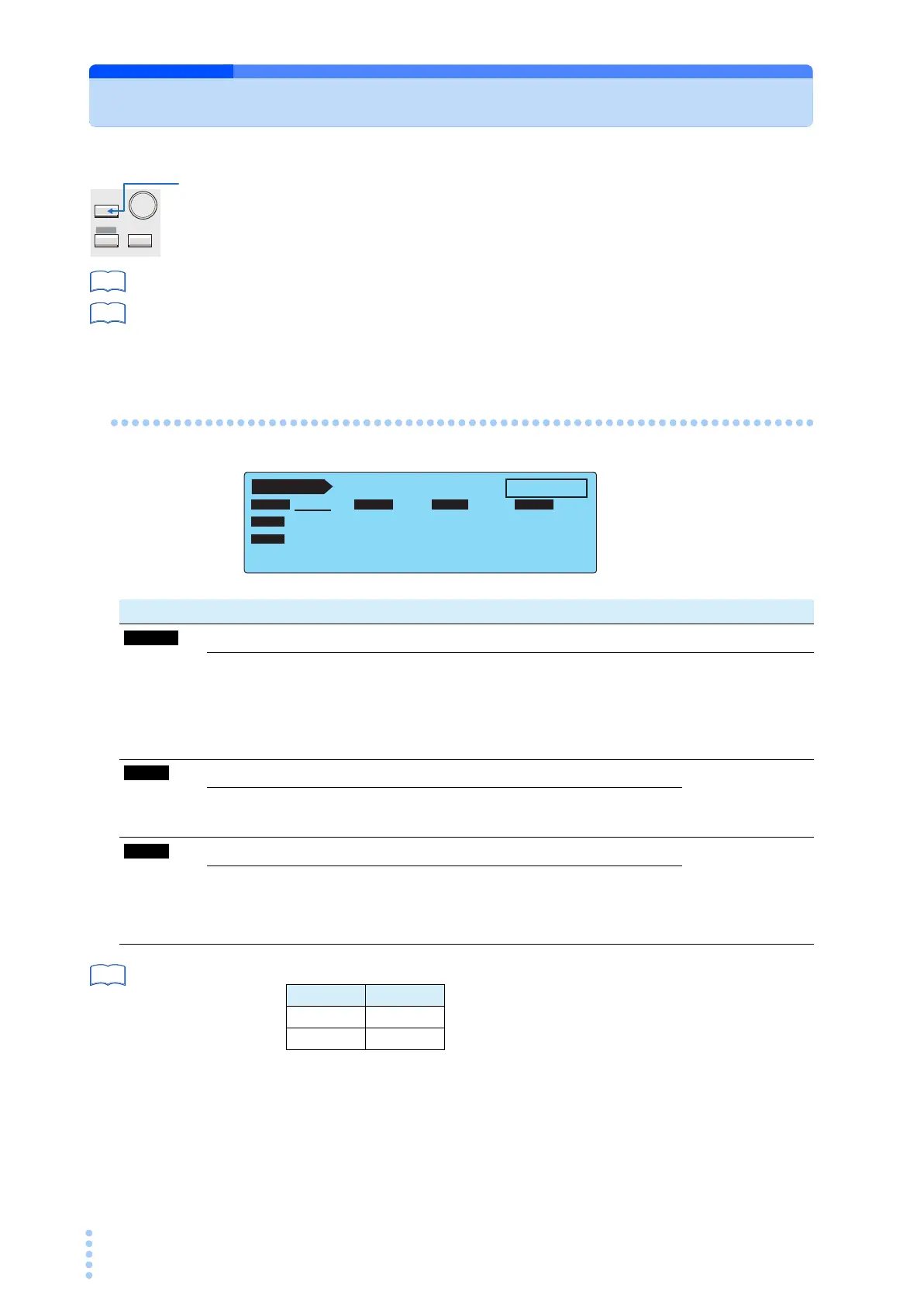
Press the MANUAL key to display the TC measurement screen 1/2 (TC1/2).
The TC measurement screen consists of two screens (TC1/2 and 2/2).
p. 31
For the procedure to select items and enter data, see “Panel Control Basics”.
p. 42
For the procedure to connect the EUT, see “Connecting the EUT”.
Setup Items of TC1/2 (PROBE / POL / COND)
Table 4-1 on p. 46
*1 The following combinations are invalid for Class II EUTs without the ground wire.
*2 If the PROBE item is set to E
NCLIV or ENCNEU, the following items cannot be selected. NORM
is selected regardless of the present setting.
SYSTEM
MANUAL
I / FEDIT
AUTO
See
See
TC 1 / 2
READY
ENCPE OFF ON
PROBE LOWER
UPPER TIMER
POL
NORM
NORM
COND
UPPER
OFF
TIMER
30.0 mA
10
s
PROBE LOWER UPPER TIME/WAIT
Item Description Panel operation
Selects the connection destination of measurement terminals A and B. PROBE (F1) key
ENCPE
*1
Between the enclosure and earth
Rotary knob
E
NCENC
*1
Between two enclosures
E
NCLIV Between the enclosure and power line (live)
E
NCNEU Between the enclosure and power line (neutral)
*2
Selects the polarity of the power line supplied to the EUT.
POL NOR/RVS
(SHIFT+F1)キー
NORM Positive phase connection
REVS Negative phase connection
*2 Selects the single fault mode.
CONDITION
(SHIFT+F2) key
NORM Normal status
FLT
NEU Power line (neutral) disconnected status
FLT
PE
*1
Earth line disconnected status
See
PROBE COND
E
NCPE FLTPE
ENCENC FLTPE