TOS3200
97
SIGNAL I/O Connector
7
External Control
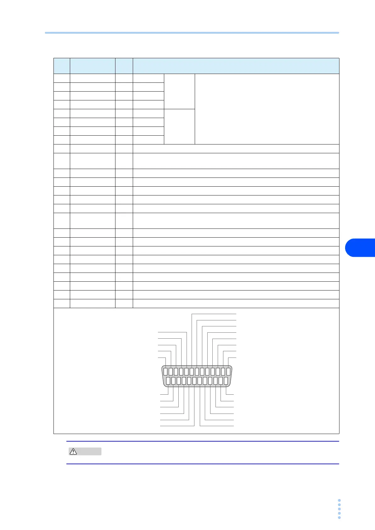
Table 7-1 SIGNAL I/O connector pin arrangement
Pin
No.
Signal name I/O Description
1PM0 I LSB
LSD
2-digit BCD low-active input
Signal input pins for selecting the panel memory or
program
This selection signal is latched on the rising edge of the
strobe signal to recall the panel memory or program.
2PM1 I –
3PM2 I –
4PM3 I –
5PM4 I –
MSD
6PM5 I –
7PM6 I –
8PM7 I MSB
9 STB I Strobe signal input terminal of the panel memory or program
10 MANU/AUTO I
Selects single test or program test.
(high: single test, low: program test)
11 STEP_END O Output at the end of each step during a program test.
12 CYCLE_END O Output at the end of the last step during a program test.
13 COM – Circuit common
14 LINE_ON O On while power is supplied from AC LINE OUT to the EUT.
15 TEST O On while the test is in progress (excluding the test wait time and interval period).
16 PASS O
On for at least 0.2 s (PASS HOLD time) when judgment is PASS.
(On continuously if the PASS HOLD time is set to HOLD.)
17 U-FAIL O Continuously on if the judgment is U-FAIL or CONTACT FAIL.
18 L-FAIL O Continuously on if the judgment is L-FAIL or CONTACT FAIL.
19 READY O On during the READY status.
20 PROTECTION O On when a protection is activated.
21 START I Start signal input pin.
22 STOP I Stop signal input pin.
23 ENABLE I Enable signal input pin of the start signal.
24 +24 V O +24-V internal power supply output terminal (maximum output current: 100 mA)
25 COM – Circuit common
Possible damage to internal circuit. Do not short the +24 V of pin number 24 to the chassis
or the circuit common.
987654321
13 12 11 10
19 18 17 16 15 1424 23 22 21 2025
PM7
PM6
PM5
PM4
PM3
PM2
PM1
PM0
LINE ON
TEST
PASS
UPPER FAIL
LOWER FAIL
READY
STB
MANU/AUTO
STEP_END
CYCLE_END
COM
COM
+24V
ENABLE
STOP
START
PROTECTION