114 Kollmorgen - December 2011
MMC Smart Drive Hardware Manual - 230V 1/3 PHASE MMC SMART DRIVE
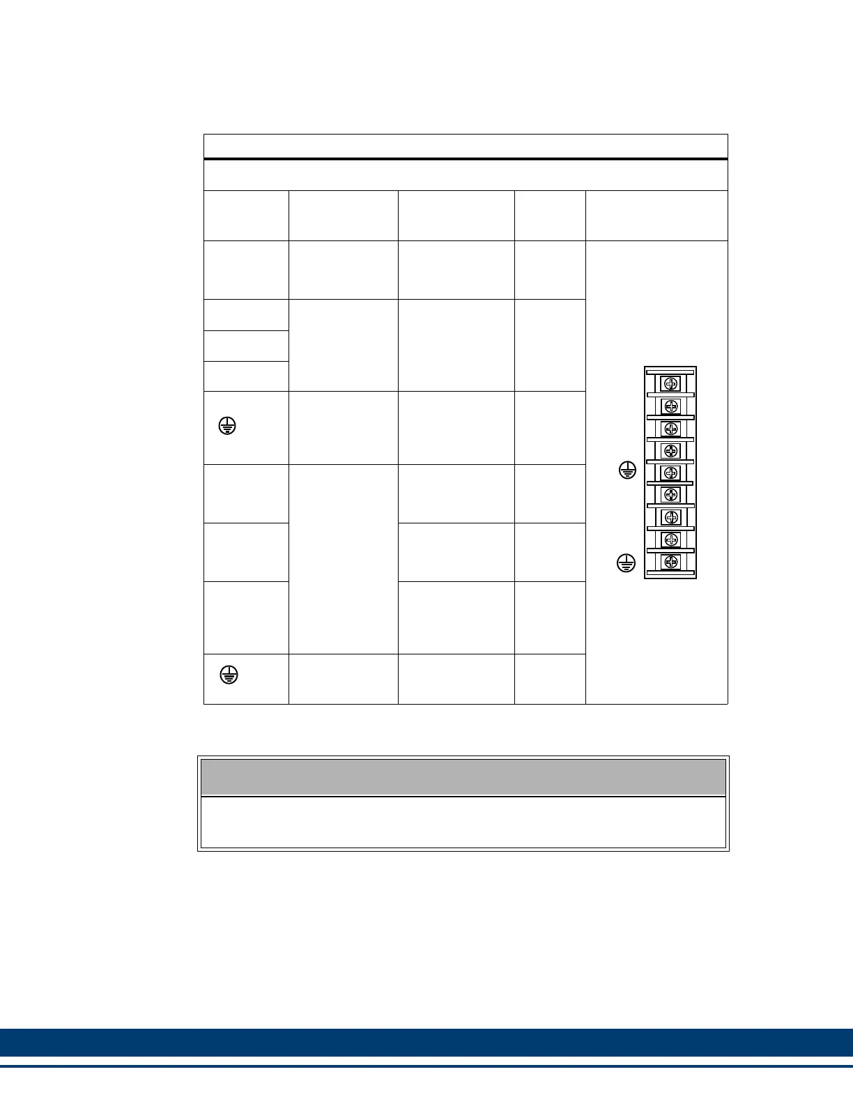
Table 5-37: Pin Assignment for 3 Phase Drive Power Connector
Three Phase Drive
Terminal
Label
Signal Type
Signal
Description
In/Out Pin Sequence
NC DC Bus
Power from
drive to active
shunt
N/A
9-pin non-plugable
Screw Terminal
L1
AC Power
100-240VAC
single or three-
phase power in
to drive.
InL2
L3
Protective
Ground
Must be con-
nected to Pro-
tective Earth
Ground (SPG).
In
U
Motor Power
Power U-phase
from the drive to
the motor.
Out
V
Power V-phase
from the drive to
the motor.
Out
W
Power W-
Phase from the
drive to the mo-
tor.
Out
Protective
Ground
Connection for
motor ground.
In
SINGLE PHASE CONNECTION
If single-phase power is used, L1 must be connected to "hot", and L2 must be
connected to "neutral". L3 may remain unconnected.
W
V
U
L3
L2
L1
NC
 Loading...