144 Kollmorgen - December 2011
MMC Smart Drive Hardware Manual - 460V 3 PHASE MMC SMART DRIVE NEXTGEN
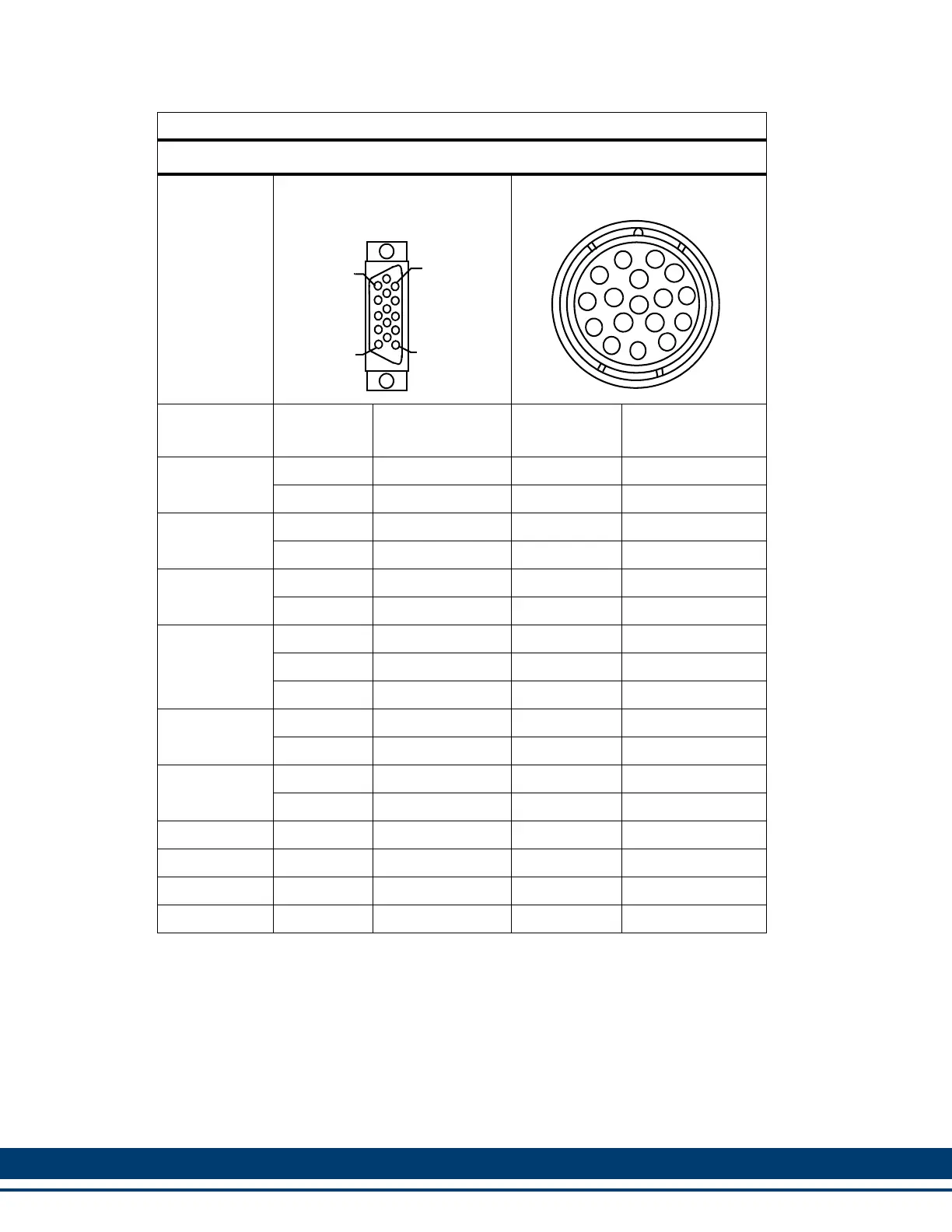
Table 6-12: Feedback Port (F1/F2) Encoder to AKM/DDR Motor
For Part Numbers, Table 6-11 on page 143
Twisted
Pair
24 AWG
(Except as
noted)
D-sub 15-Pin HD Male
Connector to MMC Smart
Drive
Connector to Motor
Wire
Color
Pin
Number
Signal Type
Pin
Number
Signal Type
Yellow 12 A 3 A
Yellow/Black 13 A/ 4 A/
Brown 14 B 1 B
Brown/Black 15 B/ 2 B/
Orange 6 I 5 I
Orange/Black 7 I/ 6 I/
Green 1
S1
a
15 S1
Black 2
S2
a
16 S2
White 3
S3
a
17 S3
Blue 8 Temperature+ 8 Temperature+
Blue/Black 9 Temperature- 9 Temperature-
Grey 4 +5V Sense+
10
b
+5V Sense+
Grey/Black 5 +5V Sense-
7
c
+5V Sense-
Red
d
10 +5 VDC
10
b
+5 VDC
Inner Braid
d
11 COM
7
c
COM
Outer Braid Shell Shield Shell Shield
N/C N/A 11-14 N/C
a. Only applicable to F2 connector
b. There are two wires in pin10
c. There are two wires in pin 7
d. This wire is 22 AWG
5
1
15
11
1
2
3
4
5
6
7
8
9
10
11
12
13
14
15
16
17
 Loading...