Kollmorgen - December 2011 149
MMC Smart Drive Hardware Manual - 460V 3 PHASE MMC SMART DRIVE NEXTGEN
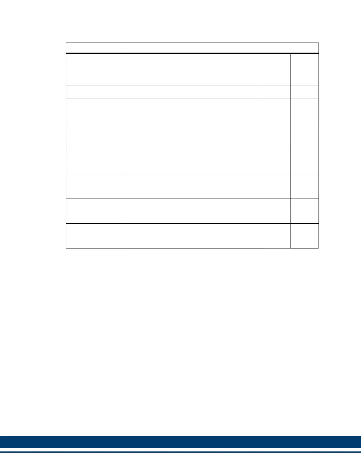
Table 6-16: Pin Description for Drive I/O Connectors (IO1 & IO2)
Signal Type Notes
IO1
Pins
IO2
Pins
Analog Input Analog Input of -10VDC to +10VDC 1, 2
Analog Output Analog Output of -10VDC to +10VDC 2, 3
General Purpose
Software Assign-
able Outputs
24VDC sourcing type 5, 6
General Purpose
Output power
24 VDC input for powering GPOUTs 7, 8
Relay Output Mechanical Relay Output 9, 10
Fast Inputs
24VDC (nominal) Inputs, configurable as Sinking
or Sourcing. Used for latching encoder position.
1, 2
Fast Input Sink/
Source
This pin determines whether the Fast Inputs are
sourcing (this pin connected to 24 Vdc) or sinking
(this pin connected to 24 Vdc Common)
3
General Purpose
Software Assign-
able Inputs
24VDC (nominal) Inputs, configurable as Sinking
or Sourcing
4, 5, 6,
7, 8, 9
General Purpose In-
puts Sink/Source
This pin determines whether the General Purpose
Inputs are sourcing (this pin connected to 24 Vdc)
or sinking (this pin connected to 24 Vdc Common)
10
 Loading...