220 Kollmorgen - December 2011
MMC Smart Drive Hardware Manual - S200-DLS DRIVE
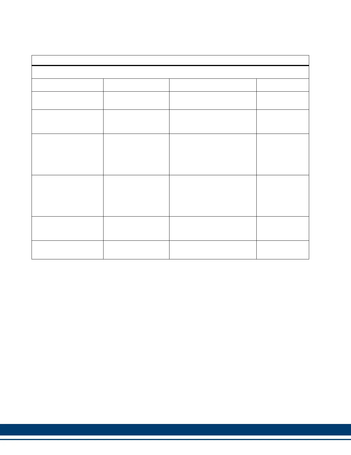
Table 8-5: Aux Feedback Port Pin Description
Aux Feedback Signals
Signal Type Signal Name Notes Pin
Incremental Encoder In-
puts
A1, A1/, B1, B1/, I1, I1/
Differential A quad B encoder
signals.
1, 2, 3, 4, 5, 10
BiSS Encoder Data
Channel In/Out
a
a. In order to use a BiSS encoder with the S200-DLS drive, the drive must be Rev 3 or later (as found on
the drive label), and the firmware within the drive must be Version 2.03 or later.
RS-485 Data +, RS-
485 Data -, RS-485
Clock+, RS-485 Clock-
RS-485 signals for connecting a
BiSS Encoder Data Channel to
the drive
5, 10, 12, 13
Motor Commutation Hall
Sensor Inputs
Commutation Track
S1, S2, S3
Hall device input signals that
are used to initialize the com-
mutation angle. They consist of
a 74HC14 input with 10μs filter
and 1 K pull up to +5V. Shared
with F2.
12, 13, 8
Temperature Input Temperature
Thermostat (normally- closed)
or Thermistor (Phillips KTY84-
130 PTC or equivalent recom-
mended) input for detecting
over temperature conditions
within the motor.
11
+5V Encoder Power Out-
puts
+5V Source
Regulated +5VDC for powering
the attached encoder (250ma
max).
14
Signal and Power Com-
mon
Common
Return path for feedback sig-
nals and +5V power supply.
6
 Loading...