Kollmorgen - December 2011 221
MMC Smart Drive Hardware Manual - S200-DLS DRIVE
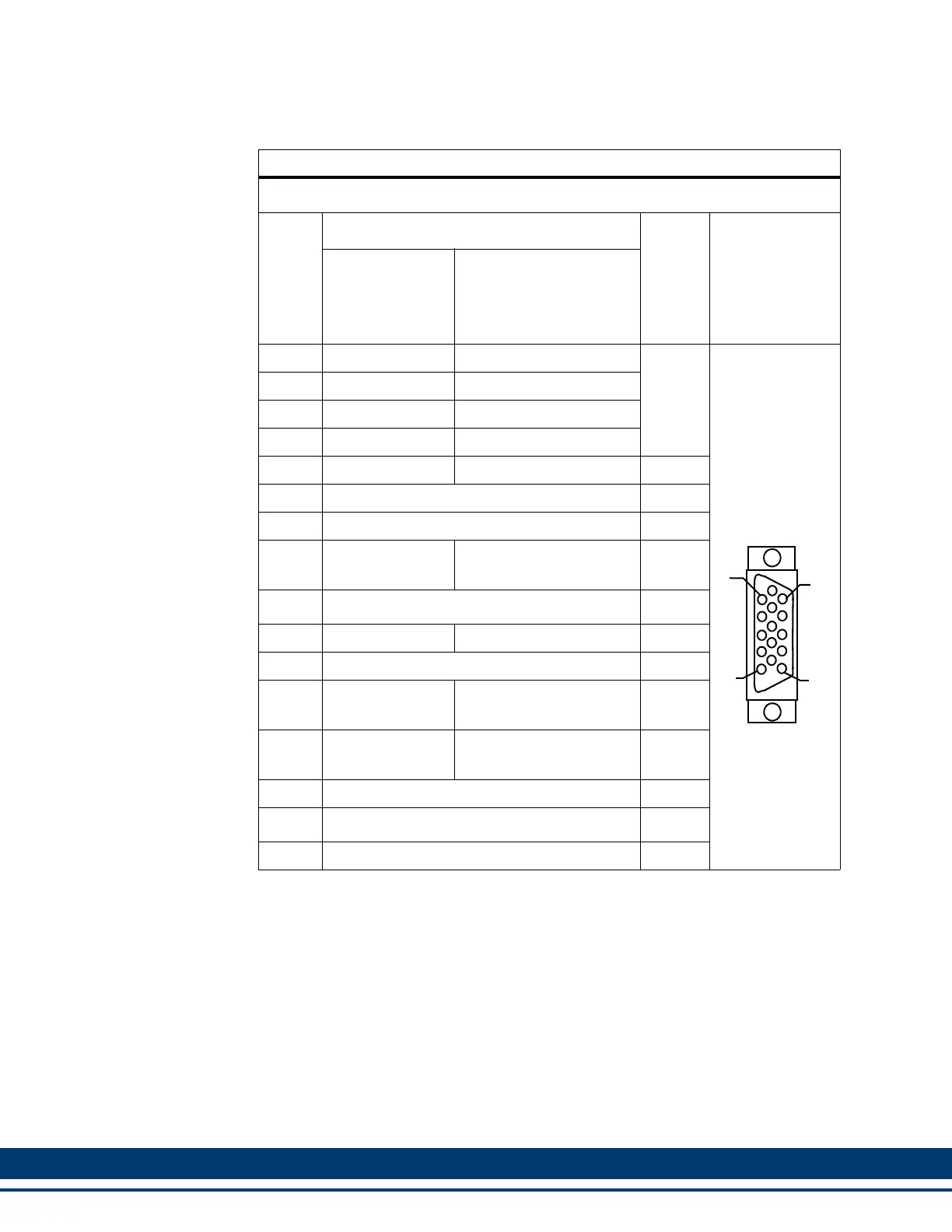
Table 8-6: Aux Feedback Port Pin Assignments
Encoder Pin Assignments for Aux Feedback 15 Pin Connector
Pin
Feedback Device
In/Out
Connector
Pinout
Digital
Incremental
Encoder
Endat
a
BISS
b
SSI
a
a. For future use
b. In order to use a BiSS encoder with the S200-DLS drive, the drive must be revi-
sion (as found on the drive label) Rev 3 or later (Rev 0 or later for 1.5A drive),
and the firmware within the drive must be Version 2.00 or later
1 A1 N/U
In
15-pin Female
HD D-Sub
2 A1/ N/U
3 B1 N/U
4 B1/ N/U
5 I1 RS-485 Data+
Note
c
c. Pins 5 and 10 are In/Out for Endat, and Inputs for Digital Incremental, SSI, and
BiSS
6 Common In/Out
7 N/U N/A
8
Commutation
Track S3
N/U In
9 N/U N/A
10 I1/ RS-485 Data-
Note
c
11 Temperature In
12
Commutation
Track S1
RS-485 Clock+
In
d
d. Pins 12 and 13 are Outputs for ENDAT, SSI, and BiSS
13
Commutation
Track S2
RS-485 Clock-
14 +5V Source Out
15 N/U N/A
Shell Shield N/A
5
1
15
11
 Loading...