Kollmorgen - December 2011 223
MMC Smart Drive Hardware Manual - S200-DLS DRIVE
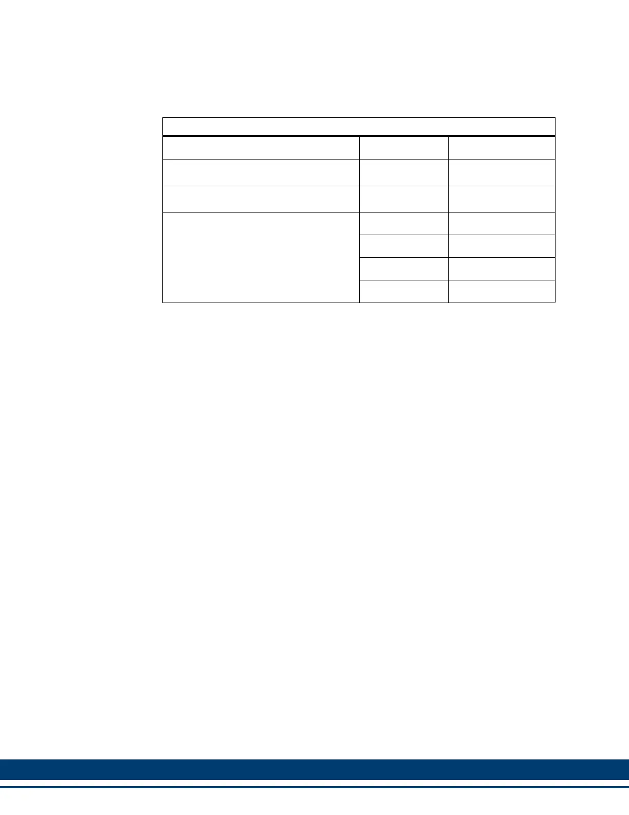
Table 8-8: Aux Feedback Port Breakout Box and Cables
Description Length Part Number
Aux Feedback Port Breakout Board
a
a. The Breakout Board (see Figure 8-3 on page 224) is mounted directly to the Aux
Feedback connector, and provides screw terminals wire termination.
N/A M.1302.6970
Aux Feedback Port Breakout Box
b
b. The Breakout Box (see Figure 8-4 on page 224) is DIN-rail mounted, and pro-
vides screw terminal wire termination. Use one of the cables listed in the table to
connect between the Aux Feedback connector and the Breakout Box.
N/A M.1302.6972
Aux Feedback Port to Breakout Box Ca-
ble
1 M (3.3 ft) M.3000.0801
3 M (9.8 ft) M.3000.0802
6 M (19.7 ft) M.3000.0803
9 M (29.7ft) M.3000.0804
 Loading...