260 Kollmorgen - December 2011
MMC Smart Drive Hardware Manual - RESOLVER INTERFACE OPTION MODULE
12. Position the Resolver Module so the long (locking tab) end of the standoffs line up
with the mounting holes on the Drive board, and the header is aligned with the
socket (See Figure1 11-2 on page 261).
13. Using even pressure, press the option module into place.
14. Verify that the module is fully seated into the socket and the locking tabs on the
standoffs are in the locked position.
15. If the Resolver Module was installed in a 230V drive, re-install the cover and five
screws removed in step 1. If the Resolver Module was installed in a 460V drive,
re-install the MMC Smart Drive board into the chassis and turn the 2 locking
screws on the front of the drive counter-clockwise to secure the front panel to the
chassis.
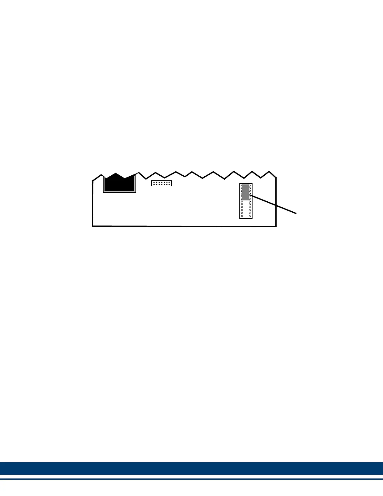
Figure 11-1: : Before Shunt Removed and Resolver Module Installed
Resolver
Board
MMC Smart
Drive Board
Shunt
Connector Side of Board
 Loading...