272 Kollmorgen - December 2011
MMC Smart Drive Hardware Manual - DRIVE RESIDENT DIGITAL MMC CONTROL
.
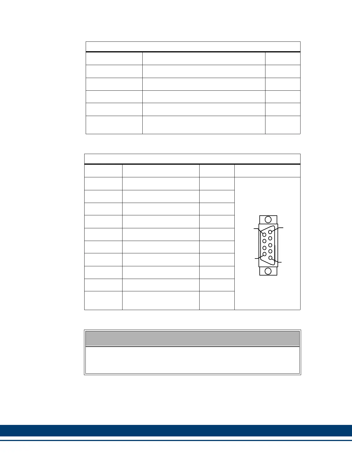
Table 12-3: Block I/O Port Pin Descriptions
Function Notes Pin
Transmit Data + Transmits data to Block I/O Modules. 3
Transmit Data - Transmits data to Block I/O Modules. 4
Receive Data + Receives data from Block I/O Modules. 5
Receive Data - Receives data from Block I/O Modules. 6
Shield Ground
Provides a path for shield current through the
chassis to an external single point ground.
7 & Shell
Table 12-4: Block I/O Port Pin Assignment
Pin Signal In/Out Connector Pinout
1 NC N/A
9-pin female D-sub
2 N/C N/A
3 Transmit Data + Out
4 Transmit Data - Out
5 Receive Data + In
6 Receive Data - In
7 Shield In
8 NC N/A
9 NC N/A
Connector
Shell
Drain In
NOTE
Pin 7 of the Block I/O port connector is connected to the connector shell with-
in the MMC. Therefore, the shield may be connected to either pin 7 or the
connector shell.
6
5
9
1
 Loading...