274 Kollmorgen - December 2011
MMC Smart Drive Hardware Manual - DRIVE RESIDENT DIGITAL MMC CONTROL
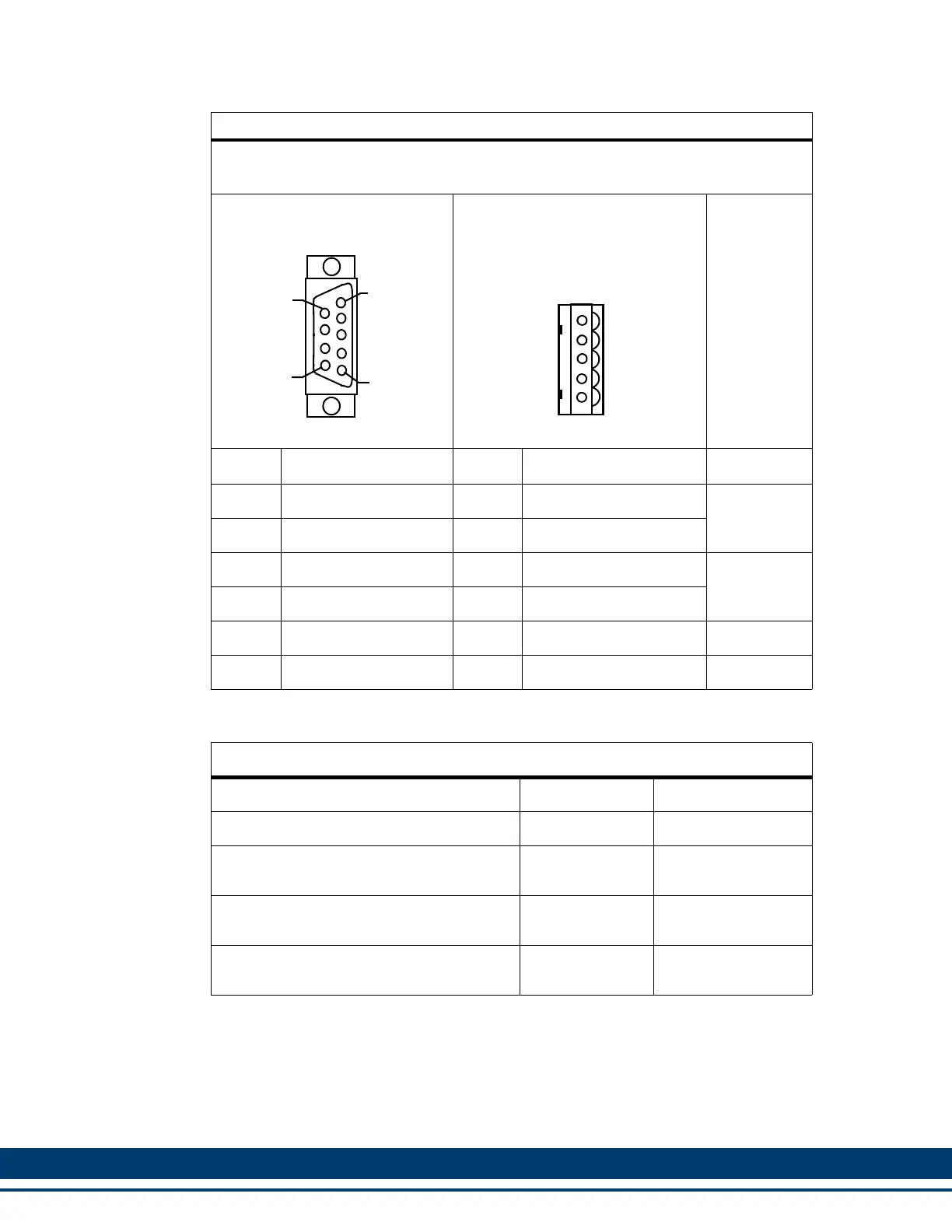
Table 12-6: Block I/O Port to Block I/O Module Wiring
Use this table to wire from the Block I/O Port to the first Block I/O
Module.
9-Pin male D-sub (to Block I/O
Port, face view)
5-Pin Pluggable Screw Terminal
(to Block I/O Module, face view)
Pin Signal Pin Signal Notes
3 Transmit Data + 1 Receive Data +
Twisted Pair
4 Transmit Data - 2 Received Data -
5 Receive Data + 4 Transmit Data +
Twisted Pair
6 Received Data - 5 Transmit Data -
7 Shield Ground 3 Shield Ground
Shell Drain Shell Drain
Table 12-7: Block I/O Port Breakout Box and Cables
a
a. The Breakout Box (see Figure 12-3 on page 275) is DIN-rail mounted, and pro-
vides screw terminal wire termination. It can be attached to the “C1” port on the
Control. The pinouts on the terminal strip interface provide a one-to-one transfer of
the signals from the connector to the respective pin(s) on the terminal block. The
connector pins marked with the “ground” symbol on the screw connector are con-
nected to the “D” connector shell for shield grounding purposes.
Description Length Part Number
MMC Block I/O Breakout Box N/A M.1016.2533
MMC Block I/O Connector to Breakout Box
Cable
.3 M (1 ft) M.1016.2543
MMC Block I/O Connector to Breakout Box
Cable
.6 M (2 ft) M.1016.2544
MMC Block I/O Connector to Breakout Box
Cable
.9 M (3 ft) M.1016.2545
1
9
5
6
1
2
3
4
5
 Loading...