Kollmorgen - December 2011 87
MMC Smart Drive Hardware Manual - 230V 1/3 PHASE MMC SMART DRIVE
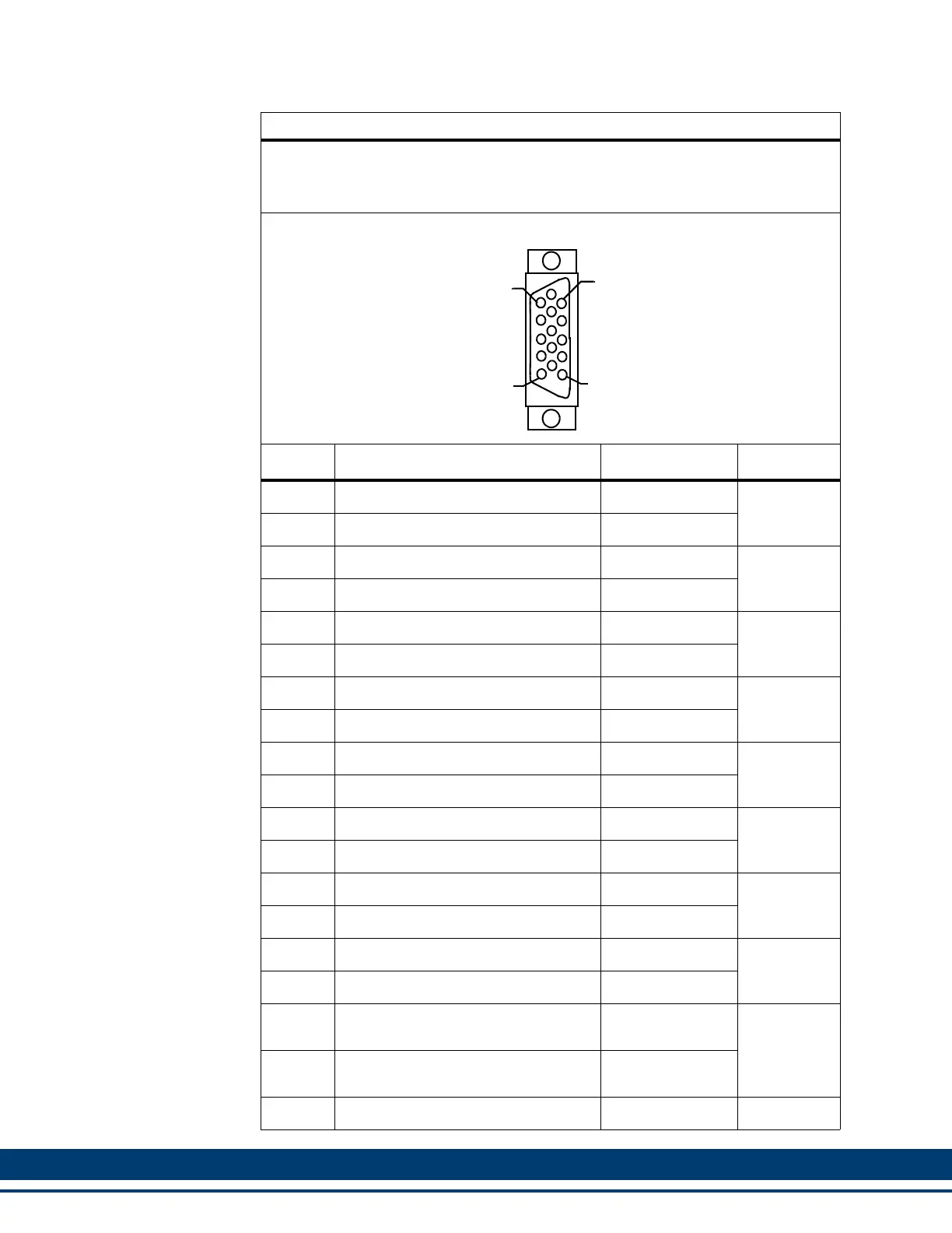
Table 5-16: Feedback Port (F1 and F2) to Flying Lead Cable
1 M (3.3 ft): M.3000.1053 3 M (9.8 ft): M.3000.1054
6 M (19.7 ft): M.3000.1055 9 M (29.5 ft): M.3000.1056
Cable type: 28 AWG, (1 pair 16 AWG) shielded, twisted pair, 16 conductor.
15-Pin HD male D-sub (to F1/F2 Port, face view)
Pin Signal Color Notes
1 A1, Cos, Cos+ Yellow Twisted
2 A1/, Cos/, Cos- White/Yellow Pair
3 B1, Sine, Sin+ Blue Twisted
4 B1/, Sine/, Sin- White/Blue Pair
5 I1, RS-485 Data+, Ref Mark, Carrier+ Black Twisted
10 I1/, RS-485 Data-, Ref Mark/, Carrier- White/Black Pair
8 Commutation Track S3 Red Twisted
NC N/A White/Red Pair
9 Commutation Cos+ Orange Twisted
15 Commutation Cos- White/Orange Pair
14 +5V source,(16 AWG) Gray Twisted
6 Common (16 AWG) White/Gray Pair
7 +9V Source Brown Twisted
NC N/A White/Brown Pair
11 Temperature Green Twisted
NC N/A White/Green Pair
12
Commutation Track S1, RS-485 Clock+,
Commutation Sin+
Violet Twisted
13
Commutation Track S2, RS-485 Clock-,
Commutation Sin-
White/Violet Pair
Shell Drain N/A
5
1
15
11
 Loading...