88 Kollmorgen - December 2011
MMC Smart Drive Hardware Manual - 230V 1/3 PHASE MMC SMART DRIVE
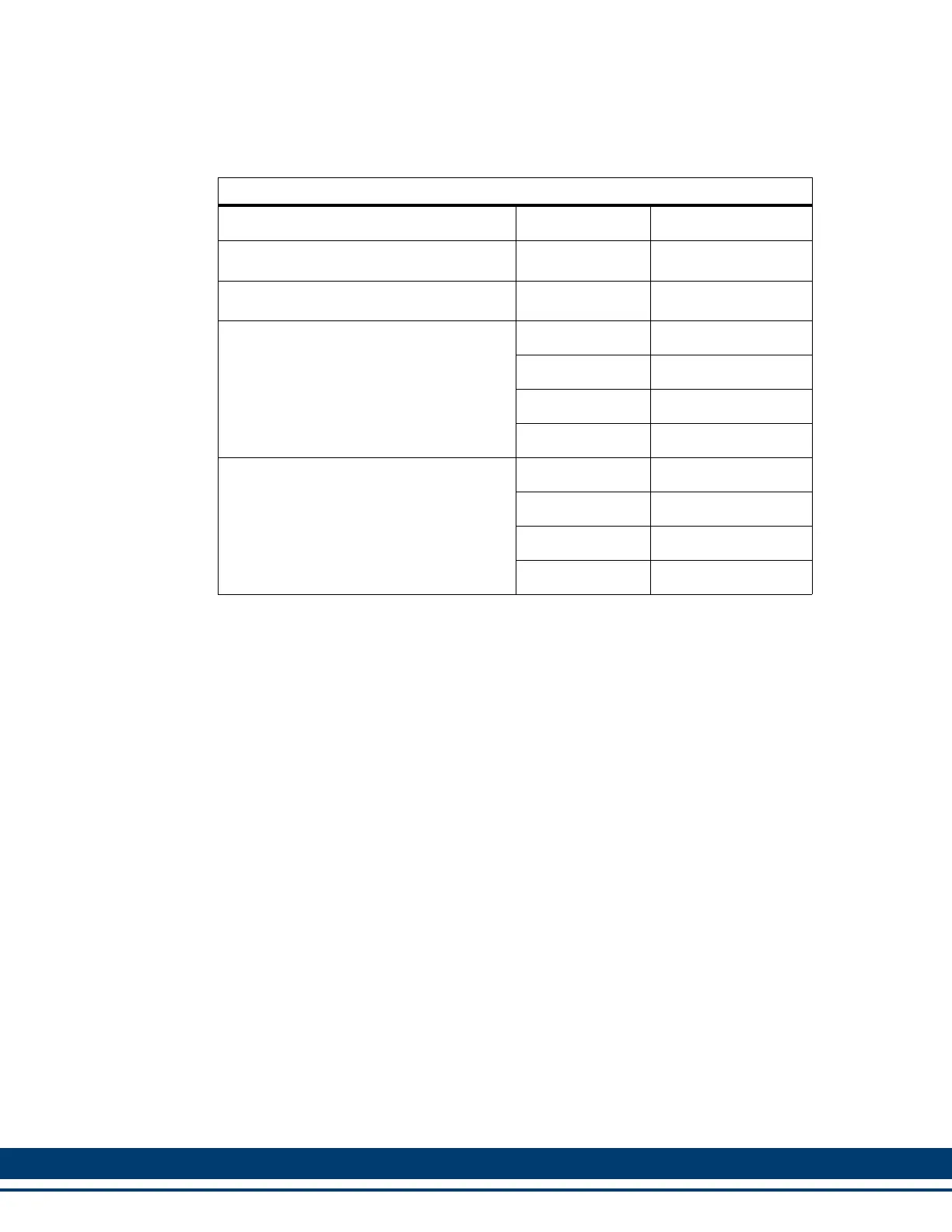
Table 5-17: Feedback Ports (F1 and F2) Breakout Box and Cables
Description Length Part Number
MMC-SD F1/F2 Port Breakout Board
a
a. The Breakout Board (see Figure 5-3 on page 89) is mounted directly to the F1
and/or F2 connector, and provides screw terminals wire termination.
N/A M.1302.6970
MMC-SD F1/F2 Port Breakout Box
b
b. The Breakout Box (see Figure 5-2 on page 89) is DIN-rail mounted, and provides
screw terminal wire termination. Use one of the cables listed in the table to con-
nect between the F1 and/or F2 connector and the Breakout Box.
N/A M.1302.6972
MMC-SD F1/F2 Port to Breakout Box
Cable
1 M (3.3 ft) M.1302.6976
3 M (9.8 ft) M.1302.6977
9 M (29.5 ft) M.1302.6979
15 M (49.2 ft) M.1302.6980
MMC-SD F1/F2 Port Breakout Box and
Cable Kits. These kits include an
M.1302.6972 Breakout Box and an inter-
connect cable of the indicated length
1 M (3.3 ft) M.1302.7005
3 M (9.8 ft) M.1302.7006
9 M (29.5 ft) M.1302.7007
15 M (49.2 ft) M.1302.7008
 Loading...