8-M4
MX5100, WSM
HYDRAULIC SYSTEM
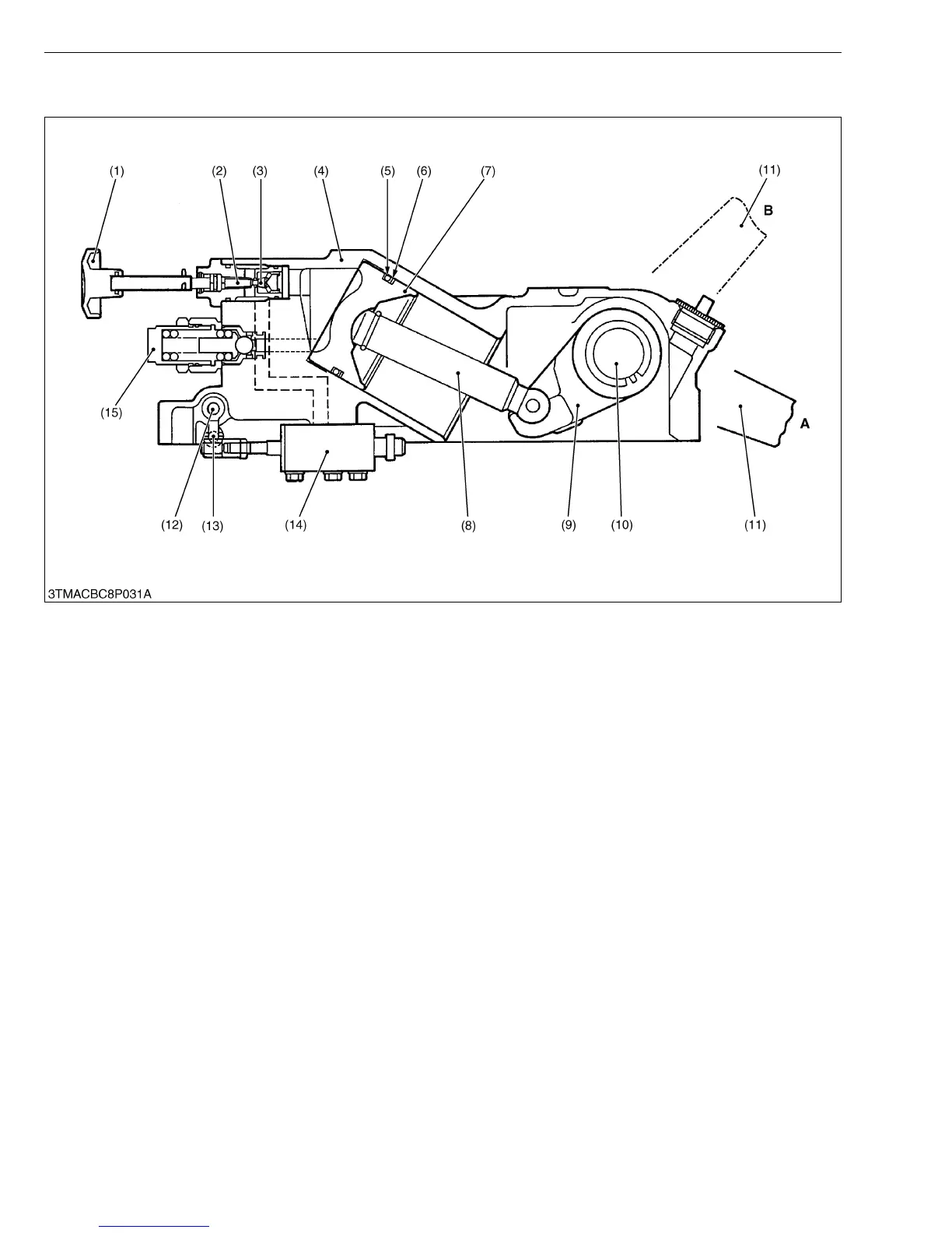
4. HYDRAULIC CYLINDER
The main components of the hydraulic cylinder are shown in the figure above.
While the lift arm (11) is rising, oil from the hydraulic pump flows into the hydraulic cylinder through the position
control valve (14). Then the oil pushes out the piston (7).
While the lift arm (11) is lowering, oil in the hydraulic cylinder is discharged to the transmission case through the
position control valve (14) by the weight of the implement. At this time, the lowering speed of the implement can be
controlled by the lowering speed adjusting knob (1) attached to the hydraulic cylinder (4). Turning the lowering speed
adjusting knob (1) clockwise decreases the lowering speed, and counterclockwise increases lowering speed. When
the lowering speed adjusting valve (3) is completely closed, the lift arm (11) is held at its position since the oil in the
hydraulic cylinder is sealed between the piston (7) and the lowering speed adjusting valve (3).
(1) Lowering Speed Adjusting
Knob
(2) Lowering Speed Adjusting
Shaft
(3) Lowering Speed Adjusting
Valve
(4) Hydraulic Cylinder
(5) O-ring
(6) Back-up Ring
(7) Hydraulic Piston
(8) Hydraulic Rod
(9) Hydraulic Arm
(10) Hydraulic Arm Shaft
(11) Lift Arm
(12) Position Control Arm
(13) Spool Drive Lever
(14) Position Control Valve
(15) Cylinder Safety Valve
A : Lift Arm “Down” Position
B : Lift Arm “Up” Position