8-M9
MX5100, WSM
HYDRAULIC SYSTEM
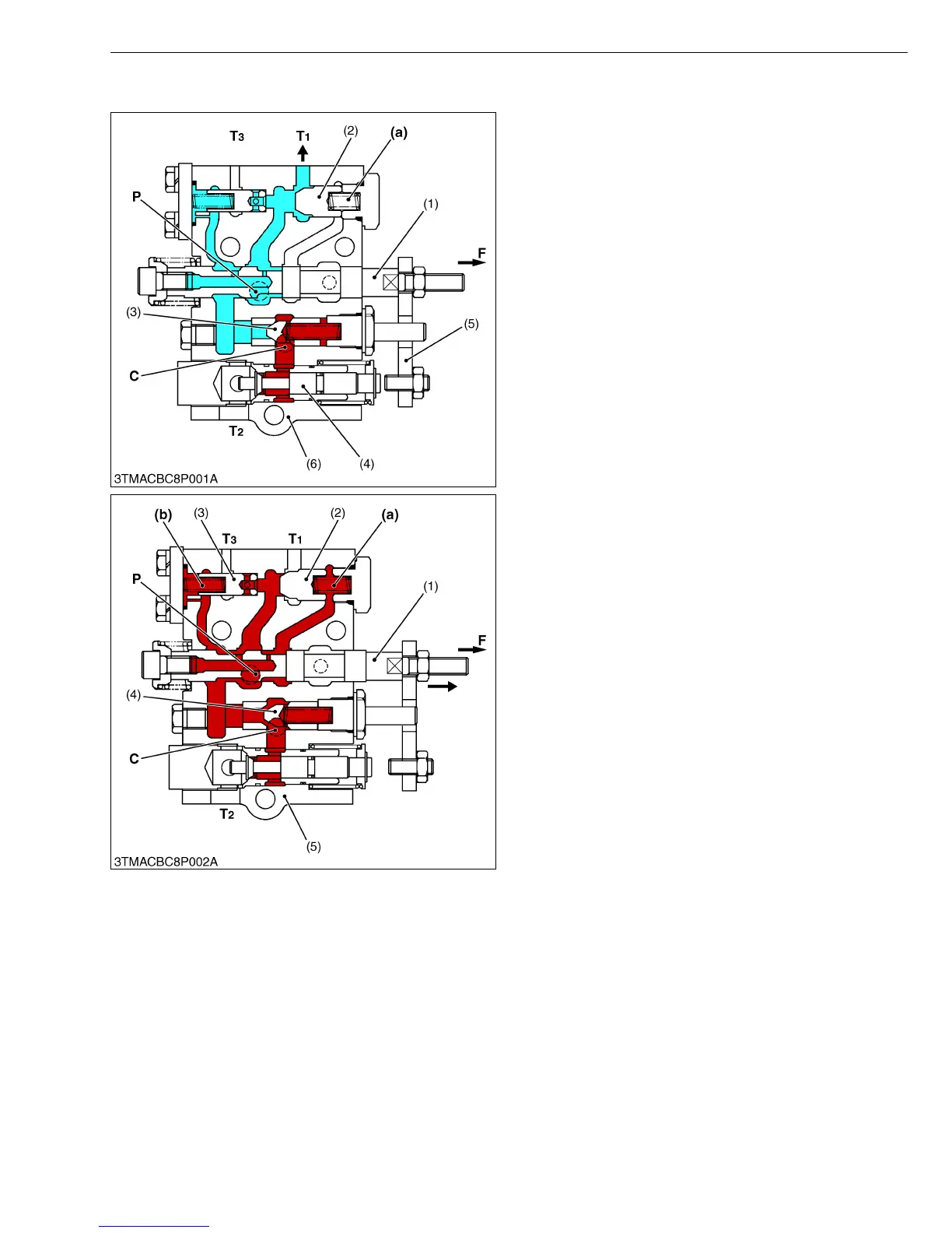
[2] POSITION CONTROL VALVE (Code No. YR908-00100) OIL FLOW
■ Neutral Position
Pressurized oil flows at the P port, pushes open
unload poppet (2) and returns to the transmission case
from T
1 port.
The oil in the A chamber (a) behind the unload poppet
(2) returns to the transmission case through the
clearance between spool (1) and control valve body (6).
The oil in the hydraulic cylinder does not flow out
because the circuit is cut off by the actions of poppet 1
(3) and poppet 2 (4).
W10155310
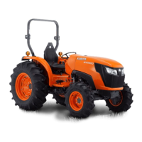
■ Lifting Position
When the control lever is moved to UP position, spool
(1) moves to arrow-mark direction. The oil entered P port
flows into the A chamber (a), B chamber (b) and closes
unload poppet (2) and poppet 3 (3).
The pressure in the circuit slowly rises, pushing open
poppet 1 (4), and the hydraulic oil flows into the hydraulic
cylinder from the C port, lifting the implement.
W10163440
(1) Spool
(2) Unload Poppet
(3) Poppet 1
(4) Poppet 2
(5) Plate
(6) Position Control Valve Body
(a) A Chamber
C : C (Cylinder) Port
P : P (Pump) Port (To Hydraulic
Pump)
T
1 :T1 Port
(To Transmission Case)
T
2 :T2 Port
(To Transmission Case)
T
3 :T3 Port
(To Transmission Case)
F : Tractor Front Side
(1) Spool
(2) Unload Poppet
(3) Poppet 3
(4) Poppet 1
(5) Position Control Valve Body
(a) A Chamber
(b) B Chamber
C : C (Cylinder) Port (To
Hydraulic Pump)
P : P (Pump) Port
T
1 :T1 Port
(To Transmission Case)
T
2 :T2 Port
(To Transmission Case)
T
3 :T3 Port
(To Transmission Case)
F : Tractor Front Side