8-M10
MX5100, WSM
HYDRAULIC SYSTEM
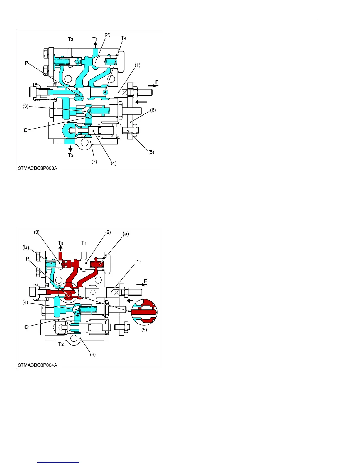
■ Lowering Position
When the control lever is moved to DOWN position,
spool (1) moves to arrow-mark direction, and poppet 2
(4) is pushed by set screw (5). As the poppet 2 (4) is
pushed, an oil circuit of C port to T
2 port is formed.
The oil in the hydraulic cylinder is forced out by the
weight of the implement, and returns to the transmission
case through the C port and T
2 port, lowering the
implement. The pressurized oil at the P port pushes
open unload poppet (2) and returns to the transmission
case from T
1 port.
■ Floating
When the control lever is moved all the way to the
bottom, spool (1) and poppet 2 (4) remain in the positions
described for “Lowering Position”. The oil flows freely
between the hydraulic pump, hydraulic cylinder and
transmission case.
W10159250
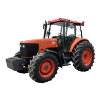
■ Lifting to Neutral
In returning from Lifting to Neutral, spool (1) is
pushed back to the arrow-mark direction. When the
neutral position comes near, the tapered part (5) of the
spool (1) makes the pressure difference at the P port and
C port. Therefore, the poppet 1 (4) gradually closes, and
absorbs any shock at lifting stop. In that case, since oil
is remained in the A chamber (a) behind the unload
poppet (2), the unload poppet (2) does not open.
However, the poppet 3 (3) opens because of low
pressure in B chamber (b), and then the oil from the
pump returns to the transmission case through T3 port.
W10166580
(1) Spool
(2) Unload Poppet
(3) Poppet 1
(4) Poppet 2
(5) Set Screw
(6) Plate
(7) Position Control Valve Body
C : C (Cylinder) Port (To
Hydraulic Pump)
P : P (Pump) Port
T
1 :T1 Port
(To Transmission Case)
T
2 :T2 Port
(To Transmission Case)
T
3 :T3 Port
(To Transmission Case)
T
4 :T4 Port
(To Transmission Case)
F : Tractor Front Side
(1) Spool
(2) Unload Poppet
(3) Poppet 3
(4) Poppet 1
(5) Tapered Part
(6) Position Control Valve Body
(a) A Chamber
(b) B Chamber
C : C (Cylinder) Port (To
Hydraulic Pump)
P : P (Pump) Port
T
1 :T1 Port
(To Transmission Case)
T
2 :T2 Port
(To Transmission Case)
T
3 :T3 Port
(To Transmission Case)
F : Tractor Front Side