9-M8
MX5100, WSM
ELECTRICAL SYSTEM
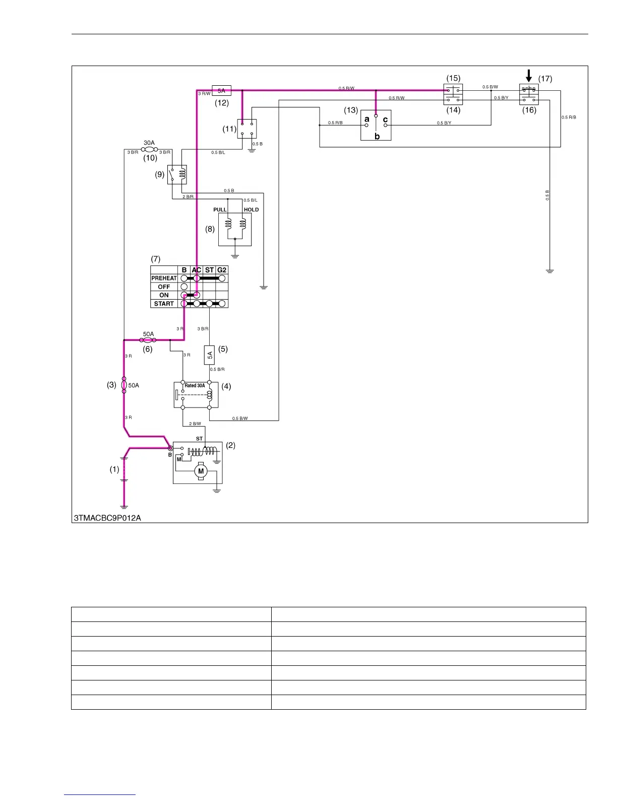
■ PTO Lever “ON”, Synchro-Shuttle Shift Lever “Neutral” and Seat “Vacant” : Engine Stops
As shown in the above electric circuit, the battery voltage does not flow to the key stop solenoid. And the pulling
and the holding coil in the key stop solenoid is not electrical magnet. The spring in the key stop solenoid pushes the
push rod and the injection pump control rack to “0” fuel injection position. And the engine stops immediately.
(1) Battery
(2) Starter
(3) Slow Blow Fuse (50A)
(4) Starter Relay
(5) Fuse (5A)
(6) Slow Blow Fuse (50A)
(7) Key Switch
(8) Key Stop Solenoid
(9) Key Stop Solenoid Relay
(10) Slow Blow Fuse (30A)
(11) OPC Timer
(12) Fuse (5A)
(13) Seat Switch
(14) PTO Neutral Switch 1
(15) PTO Neutral Switch 2
(16) Shuttle Lever Neutral Switch 1
(17) Shuttle Lever Neutral Switch 2
a : Seated
b : Vacant
c : Turn Over
PTO lever at “ON” PTO neutral switch 2 (15) “OFF”
Range shift lever “Neutral” Shuttle lever neutral switch 1 (16) “ON”
Seat “Vacant” Seat switch (13) “OFF”
OPC timer (11) OPC timer switch (11) “OFF”
Key stop solenoid relay (9) Key stop solenoid relay (9) switch “OFF”
Key stop solenoid (8) Not energized
Engine Running stops (control rack is pushed to fuel “0” position by the key stop solenoid.)