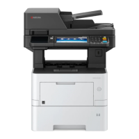
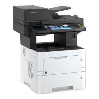
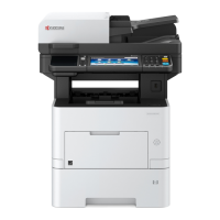
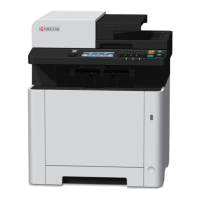
2NM/2NX/2NY/2NZ/2P0/2P6
2-2-59
(3) Connector lists
Connector Pin Signal I/O Voltage Description
YC1
1 GND - - Ground
Connected to
the control
PWB
2 3.3V1_C I 3.3 V DC 3.3 V DC power input
3 LCDCON I 0/3.3 V DC LCD control signal
4 5.0V2_C I 5V DC 5 V DC power input
5 PAN_RXD O 0/3.3 V DC Serial communication data signal
6 PAN_TXD I 0/3.3 V DC Serial communication data signal
7 AUDIO I Analog AUDIO signal
8 FPRST I 0/3.3 V DC Panel reset signal
9INT_POWER
KEY
O 0/3.3 V DC Power key: On/Off
10 GND - - Ground
YC2
1 +5V5 O 5V DC 5 V DC power output
Connected to
the back light
PWB
2 BLIGHT O 5 V DC BLPWB: On/Off
YC3
1 WETCLK O 0/3.3 V DC (pulse) Humid sensor clock signal
Connected to
the control
PWB
2 GND - - Ground
3 AIRWET O Analog Humid sensor input signal
4 AIRTEMP O Analog Temperature sensor input signal
YC4
1 SPK+ O Analog Speaker sound signal (+)
Connected to
the speaker
(FAX model
only)
2 SPK- O Analog Speaker sound signal (-)
 Loading...
