LDI Intellectual Property.
Not for secondary distribution or replication, in part or entirety.
DIGISONDE-4D
SYSTEM MANUAL
VERSION 1.2.11
SECTION 3 - OPERATING INSTRUCTIONS 3-11
3:12. For example, suppose 50 kHz linear frequency stepping and x4 advantage in Doppler resolution is re-
quired for an ionogram. Then fine frequency step (FFS) is 50 kHz, number of fine steps (NFS) is 4, and coarse
frequency step is CFS = NFS * FFS = 200 kHz. The same ionogram measurement but without x4 Doppler reso-
lution improvement would be made by setting CFS to 50 kHz and NFS to “none” (thus disabling multiplexing).
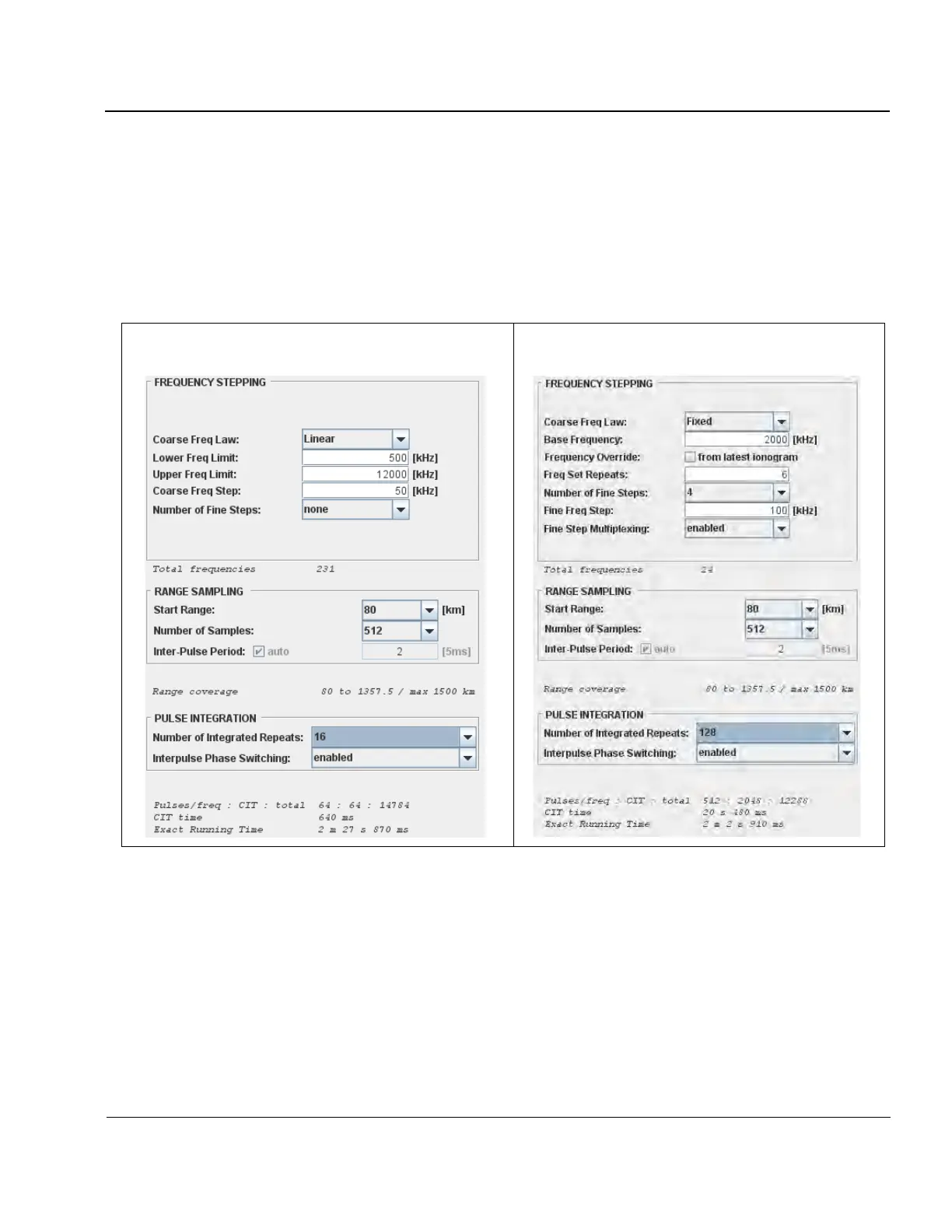
3:13. Frequency Stepping, Range Sampling, and Pulse IntegrationFigure 3-5 compares two typical examples
of programming frequency/range stepping & pulse integration for ionogram & drift modes.
Figure 3-5: Programming Frequency Stepping and Range Sampling for Ionogram and
Drift Measurements
3:14. The left panel of Figure 3-5 specifies a frequency sweep from 0.5 to 12 MHz, typical for the ionogram
mode. Frequency multiplexing is disabled, and linear frequency stepping with 50 kHz is set, resulting in 231
frequency steps in the ionogram. Interpulse period of 2 x 5 ms = 10 ms (1500 km radar range) is selected to
accommodate 512 range steps of 2.5 km each (from 80 to 1357.5 km). Number of integrated repeats per fre-
quency is set to 16, resulting in the Doppler spectra with 16 lines. Each integrated repeat involves 2 pulses with
complementary codes of phase modulation, and two separate transmissions for O and X polarizations. Thus 64
pulses are transmitted on each frequency, totaling 64 x 231 = 14784 pulses needed to complete the ionogram
measurement. At 10 ms interpulse period, pulse transmission during this ionogram requires 14784 x 10 ms =
147.84 sec = 2m 27s 840ms. Additional 30 ms of time overhead are required to manage FIFO buffers and time
 Loading...