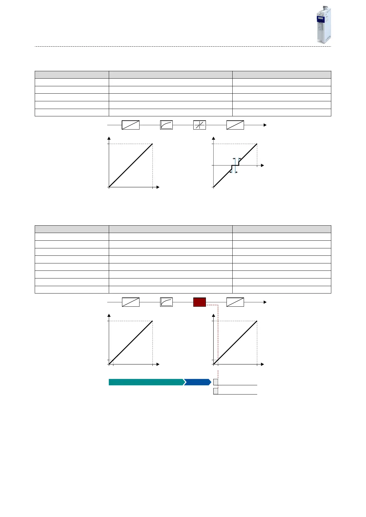
10.2.1.2 Example: Input range 0 ... 10 V = seng range -40 ... +40 Hz
In this example, a bipolar seng range and a dead band with 2 % are congured.
Parameter Designaon Seng for this example
0x2636:001 (P430.01) Analog input 1: Input range 0 ... 10 VDC [0]
0x2636:002 (P430.02) Analog input 1: Min frequency value -40.0 Hz
0x2636:003 (P430.03) Analog input 1: Max frequency value 40.0 Hz
0x2636:006 (P430.06) Analog input 1: Filter me 10 ms
0x2636:007 (P430.07) Analog input 1: Dead band 2.0 %
10
0
100
[%]
[V]
0
100
0
40
-40
2 %
[Hz]
[%]
2 %
0
AI1
%
Hz
V
%
10 ms
2 %0 ... 10 VDC -40 ... 40 Hz
10.2.1.3 Example: Error detecon
In this example, the digital output 1 is set via the trigger "Error of analog input 1 acve [81]" if
the per
centage input value is lower than 10 %. Addionally, a warning is output.
Parameter Designaon Seng for this example
0x2634:002 (P420.02) Digital outputs funcon: Digital output 1 Error of analog input 1 acve [81]
0x2636:001 (P430.01) Analog input 1: Input range 0 ... 10 VDC [0]
0x2636:002 (P430.02) Analog input 1: Min frequency value 0.0 Hz
0x2636:003 (P430.03) Analog input 1: Max frequency value 40.0 Hz
0x2636:006 (P430.06) Analog input 1: Filter me 10 ms
0x2636:008 (P430.08) Analog input 1: Monitoring threshold 10.0 %
0x2636:009 (P430.09) Analog input 1: Monitoring condion Input value < trigger threshold [0]
0x2636:010 (P430.10) Analog input 1: Error response Warning [1]
10
0
100
[%]
[V]
0
10
1
0x2634:002
100
0
40
[Hz]
[%]
0
4
10
AI1
%
Hz
V
%
10 ms0 ... 10 VDC 0 ... 40 Hz
< 10 %
Warning "Error of analog input 1"
Error of analog input 1 active [81]
Status signal Digital output 1
I/O extensions and control connecons
Congure analog inputs
Analog input 1
208

 Loading...


