Address Name / seng range / [default seng] Informaon
0x2DAC
(P119.00)
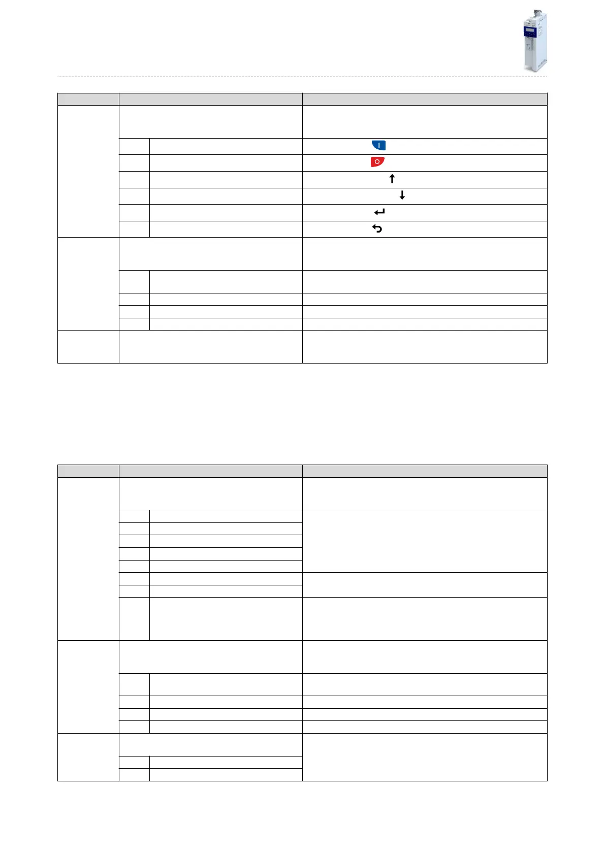
Keypad status
(K
eypad status)
•
Read only
Bit-coded display of the keypad status.
Bit 0 Start Key
1 = keypad start key
pressed.
Bit 1 Stop Key
1 = keypad stop key pressed.
Bit 2 Up arrow
1 = keypad up-arrow key pressed.
Bit 3 Down arrow
1 = keypad down-arrow key pressed.
Bit 4 Enter Key
1 = keypad enter key pressed.
Bit 5 Back key
1 = keypad back key pressed.
0x2DAD
(P120.00)
Internal hardware states
(In
t. HW states)
•
Read only
Bit-coded display of internal hardware states.
Bit 0 Relay 0 = X9/NO-COM open and NC-COM closed.
1 = X9/NO-COM closed and NC-COM open.
Bit 1 Digital output 1 0 = LOW level, 1 = HIGH level.
Bit 2 Digital output 2 Funcon is not supported in this device.
Bit 10 Charge Relay 1 ≡ precharging of the DC bus via charge relay is acve.
0x603F
(P150.00)
Error code
(Error code)
•
Read only
Error message
14.4.2 I/O
diagnoscs
This secon describes the diagnoscs of the analog and digital inputs and outputs that can be
found on the control terminal X3.
14.4.2.1 Digital inputs and outputs
The following parameters serve to diagnose the digital inputs and outputs of the inverter.
Parameter
Address Name / seng range / [default seng] Informaon
0x60FD
(P118.00)
Digital inputs
(Digit
al inputs)
•
Read only
Bit coded display of the current state of the digital inputs
Bit 16 Level from digital input 1 0 = LOW level, 1 = HIGH level.
Bit 17 Level from digital input 2
Bit 18 Level from digital input 3
Bit 19 Level from digital input 4
Bit 20 Level from digital input 5
Bit 21 Level from digital input 6 Not available
Bit 22 Level from digital input 7
Bit 25 Internal interconnecon of digital inputs 0 = digital input terminals are set to HIGH (PNP) level via pull-up
resistors.
1 = digital input terminals are set to LOW (PNP) level via pull-down
resistors.
0x2DAD
(P120.00)
Internal hardware states
(Int. HW states)
•
Read only
Bit-coded display of internal hardware states.
Bit 0 Relay 0 = X9/NO-COM open and NC-COM closed.
1 = X9/NO-COM closed and NC-COM open.
Bit 1 Digital output 1 0 = LOW level, 1 = HIGH level.
Bit 2 Digital output 2 Funcon is not supported in this device.
Bit 10 Charge Relay 1 ≡ precharging of the DC bus via charge relay is acve.
0x4016:005 Digital output 1: Terminal state
•
Read only
Display of the logic state of output terminal X3/DO1.
0 FALSE
1 TRUE
Diagnoscs and fault eliminaon
Diagnosc parameters
In
verter diagnoscs
278

 Loading...


