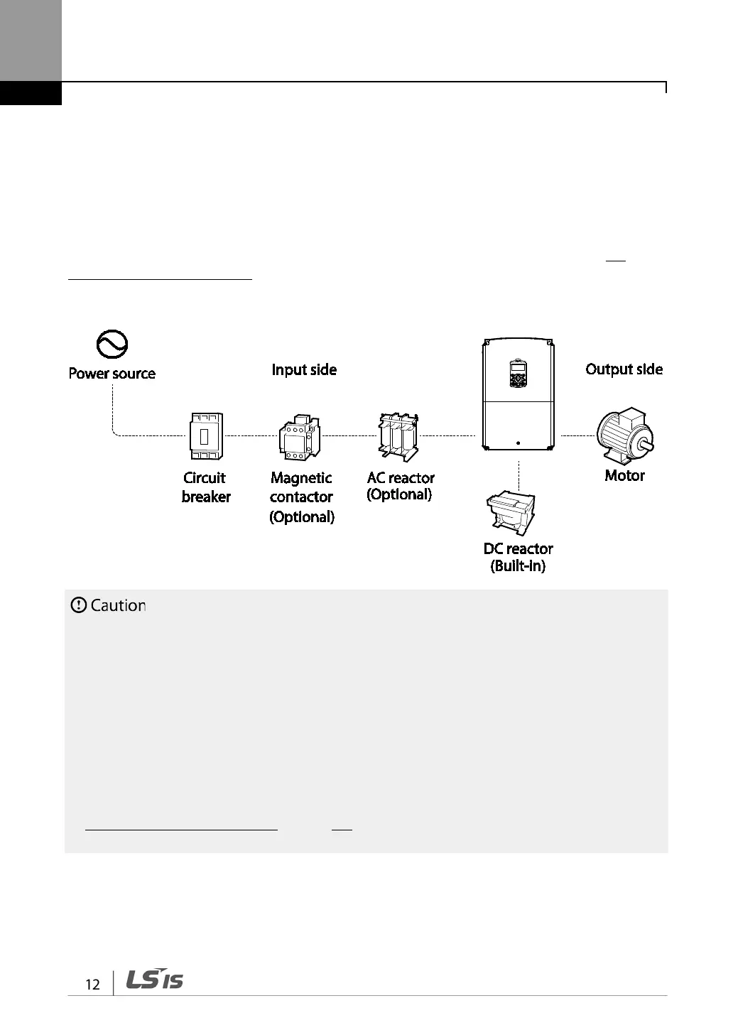
Basic Configuration Diagram
The reference diagram below shows a typical system configuration showing the inverter and
peripheral devices.
Prior to installing the inverter, ensure that the product is suitable for the application (power rating,
capacity, etc). Ensure that all of the required peripherals and optional devices (resistor brakes,
contactors, noise filters, etc.) are available. For more details on peripheral devices, refer to 9.4
Peripheral Devices on page 253.
• Figures in this manual are shown with covers or circuit breakers removed to show a more detailed
view of the installation arrangements. Install covers and circuit breakers before operating the
inverter. Operate the product according to the instructions in this manual.
• Do not start or stop the inverter using a magnetic contactor, installed on the input power supply.
• If the inverter is damaged and loses control, the machine may cause a dangerous situation. Install an
additional safety device such as an emergency brake to prevent these situations.
• High levels of current draw during power-on can affect the system. Ensure that correctly rated circuit
breakers are installed to operate safely during power-on situations.
• Reactors can be installed to improve the power factor. Note that reactors may be installed within 30
ft (9.14 m) from the power source if the input power exceeds 10 times of inverter capacity. Refer to
9.5 Fuse and Reactor Specifications on page 253 and carefully select a reactor that meets the