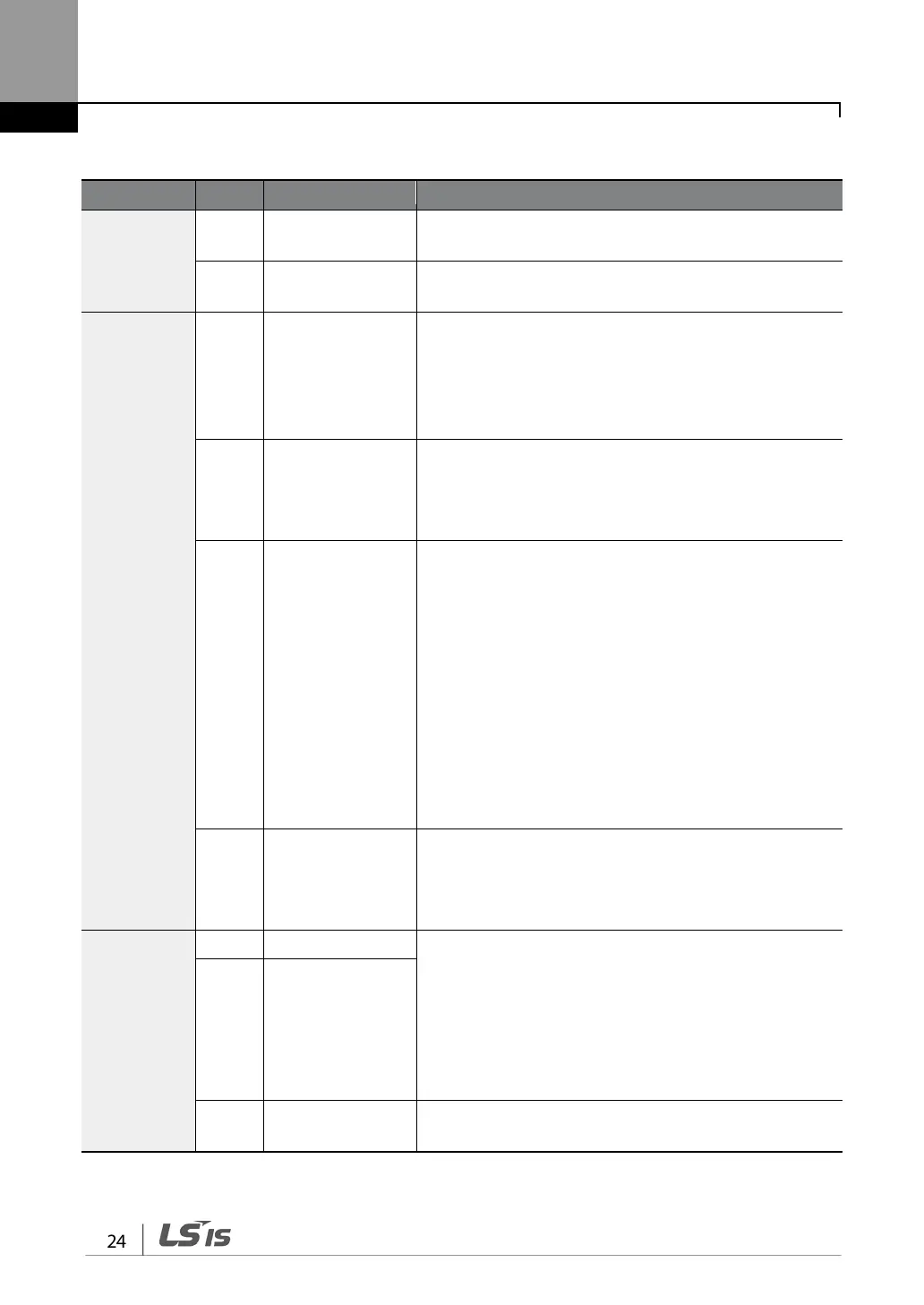
Input Terminal Labels and Descriptions
Multi-
function
terminal
configuration
P1–P7
Configurable for multi-function input terminals.
CM
Common terminal for analog terminal inputs and
outputs.
Analog input
configuration
VR
Potentiometer
frequency
reference input
Used to setup or modify a frequency reference via analog
voltage or current input.
• Maximum Voltage Output: 12 V
• Maximum Current Output: 100 mA,
•
V1
Voltage input for
frequency
reference input
Used to setup or modify a frequency reference via analog
voltage input terminal.
• Unipolar: 0–10 V (12 V Max.)
•
Bipolar: -10–10 V (±12 V Max.)
I2
Voltage/current
input for frequency
reference input
Used to setup or modify a frequency reference via analog
voltage or current input terminals.
Switch between voltage (V2) and current (I2) modes
using a control board switch (SW2).
V2 Mode:
• Unipolar: 0–10 V (12 V Max.)
I2 Mode
• Input current: 4–20 mA
• Maximum Input current: 24 mA
TI
Pulse input for
frequency
reference input
(pulse train)
Setup or modify frequency references using pulse inputs
from 0 to 32 kHz.
• Low Level: 0–2.5 V
Safety
functionality
configuration
Used to block the output from the inverter in an
emergency.
Conditions:
• Normal Operation: Both the SA and SB terminals are
connected to the SC terminal.
•
Output Block: One or both of the SA and SB terminals
lose connection with the SC terminal.
SB Safety input B
SC
Safety input power
source
DC 24 V, < 25 mA