EasyManua.ls Logo

LSIS XEC-DP64H User Manual

LSIS XEC-DP64H
315 pages
To Next Page IconTo Next Page
To Previous Page IconTo Previous Page
Page #105 background imageLoading...
Page #105 background image
Chapter 5 Positioning Instructions
5 - 6
(d) Program Operation
The ORG instruction is executed when there is the rising edge of M0000 which was used as the
starting signal of the axis X origin return.
(It doesn’t work if axis X is operating or in error)
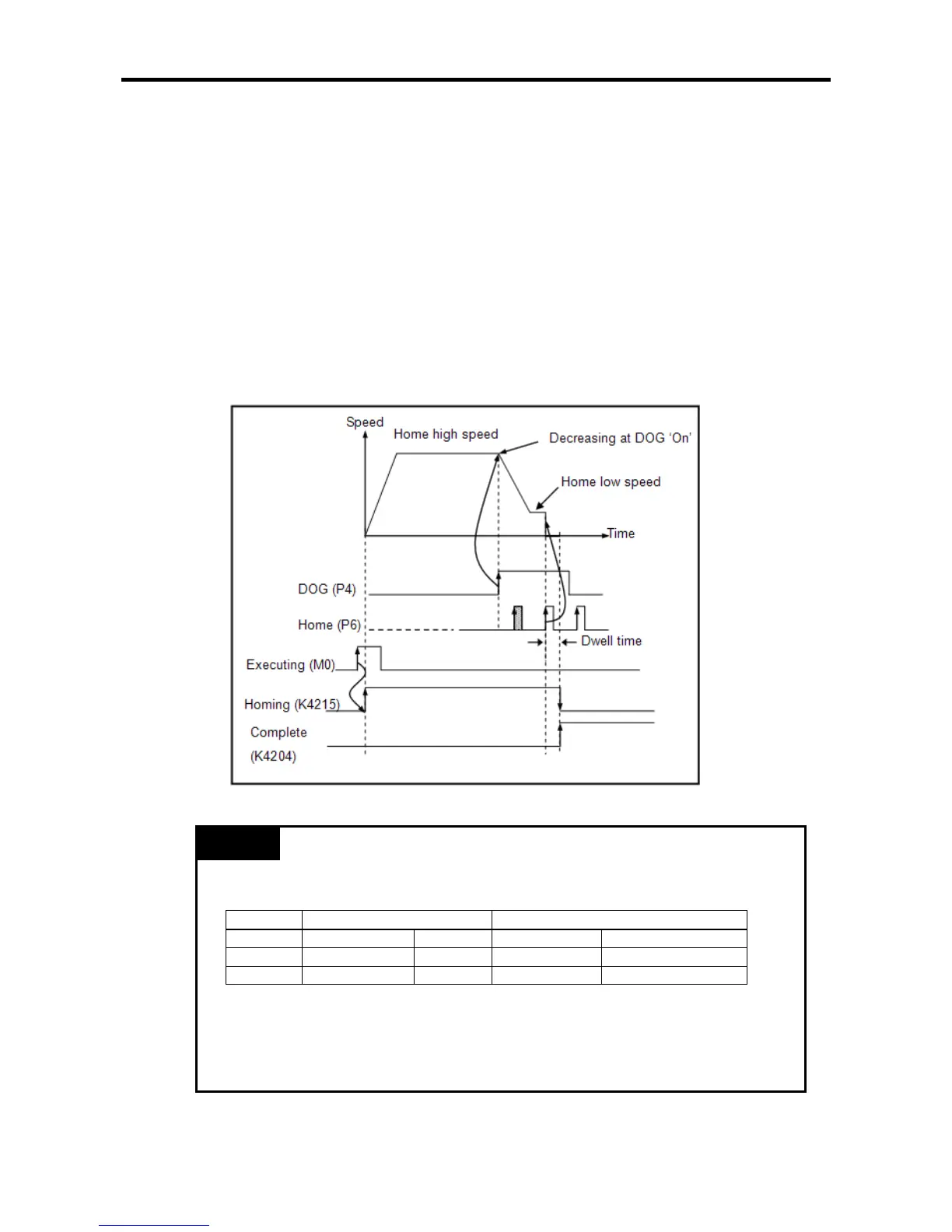
1) If the origin return instruction (ORG instruction) is executed, it is decelerated in the reverse
direction as set in the origin return parameter and operates at origin return high speed
(50,000pps).
2) If there is the rising edge of the DOG signal during origin return high speed operation, it is
decelerated and operates at origin return low speed (500pps). The deceleration time is 100ms,
set in the parameter.
3) If the origin signal is input, which is the external input signal, after switch to the origin return low
speed, the output immediately stops, and the origin determining status flag (K4204 bit) turns
On after the dwell time (100ms).
(There may be a delay as long as ‘dwell time + 1 scan time’ until the origin determining status
flag (K4204 bit) turns On after the output stops.)
4) Then the current address is preset at 0, which is the origin address set in the parameter.
Remark
The DOG signal and origin signal are respectively fixed as the following contact points.
Standard
Compact standard/high-end type
DOG
origin
DOG
origin
axis X
P0004
P0005
P000C
P000D
axis Y
P0006
P0007
P000E
P000F
If the contact points of the DOG and the origin input are used together as the external
preset input of the high speed counter, or together as the starting signal of the external
contact point task, the origin detection might be inaccurate.
The current position address does not change during origin return.

Table of Contents

Questions and Answers:

LSIS XEC-DP64H Specifications

General IconGeneral
BrandLSIS
ModelXEC-DP64H
CategoryController
LanguageEnglish

Summary

XGB Built-in Positioning

Safety Instruction

Crucial safety guidelines to be followed before operating the product.

Chapter 1 General

Provides general information about the positioning function, including purpose and features.

Chapter 2 General Specification

Provides general specifications for the XGB series, including environmental and immunity details.

Chapter 3 Before Positioning

Explains various positioning functions, parameters, and operation data.

Chapter 4 Positioning Check

Outlines the procedure for testing XGB positioning operation before use.

Chapter 5 Positioning Instructions

Provides detailed explanations for various positioning instructions like Origin Return, Direct Start, etc.

Chapter 6 Positioning Monitoring Package

Introduces the XGB positioning monitoring package for status monitoring and test operation.

Chapter 7 Program Examples of Positioning

Provides practical program examples for various positioning functions.

Chapter 8 Troubleshooting Procedure

Outlines basic steps for troubleshooting errors in XGB PLC and positioning functions.

Appendix 1 List of Error Codes

Details specific error codes related to the XGB positioning function.

Appendix 2 Positioning Instruction and K area List

Provides a list of dedicated K areas for positioning parameters and instructions.

Appendix 3 Motor Wiring Example

Illustrates wiring examples for connecting XGB PLC to servo motors.

Appendix 4 Dimension

Provides dimensional drawings for standard XGB main units (XBM-DN/DR series).

Related product manuals