EasyManua.ls Logo

LSIS XEC-DP64H User Manual

LSIS XEC-DP64H
315 pages
To Next Page IconTo Next Page
To Previous Page IconTo Previous Page
Page #106 background imageLoading...
Page #106 background image
Chapter 5 Positioning Instructions
5 - 7
5.2.2 Floating Origin Setting Instruction
Floating origin setting refers to setting the current position as the origin by force with the instruction
without carrying out the actually mechanical origin return.
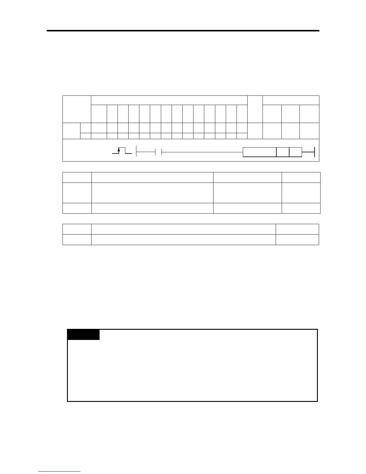
(1) Floating origin Setting Instruction (FLT)
[Area Setting]
Operand
Description
Setting range
Data size
sl
Slot number where positioning module is
mounted
XGB is fixed at 0 WORD
ax
Axis to give instruction
0(axis X) or 1(axis Y)
WORD
[Flag Set]
Flag
Description
Device number
Error
If the value of ax gets out of the range
F110
(a) Function
This instruction is for setting the floating origin to the XGB built-in positioning.
The instruction of setting the floating origin is given to the axis designated as ax of XGB positioning
at the rising edge of the input condition.
If the instruction is carried out, the current position address becomes 0, and the origin determining
bit (axis X: K4204,axis Y:K4304) turns On.
(b) Error
If the value designated as ax (instruction axis) is other than 0 and 1, the error flag (F110) is set and
the instruction is not executed
Remark
Floating origin setting presets the current position at 0 and only fixs the origin, so you need to
note the following when you use the instruction of setting the floating origin.
Check whether there is an error before carrying out the floating origin setting instruction. If
there is an error, remove the cause of the error, reset the error (CLR instruction) and
terminate the output inhibition.
Now set the floating origin, change the step number to operate into the starting step change
instruction (SNS), and then get it started.
Instruction
Areas available
Step
Flag
PMK F L T C S Z D.x R.x
con
stan
t
U N D R
Error
(F110)
Zero
(F111)
Carry
(F112)
FLT
sl - - - - - - - - - - - - -
4~7 - -
ax
-
-
-
-
-
-
-
-
-
FLT
COMMAND
FLT
sl
ax

Table of Contents

Questions and Answers:

LSIS XEC-DP64H Specifications

General IconGeneral
BrandLSIS
ModelXEC-DP64H
CategoryController
LanguageEnglish

Summary

XGB Built-in Positioning

Safety Instruction

Crucial safety guidelines to be followed before operating the product.

Chapter 1 General

Provides general information about the positioning function, including purpose and features.

Chapter 2 General Specification

Provides general specifications for the XGB series, including environmental and immunity details.

Chapter 3 Before Positioning

Explains various positioning functions, parameters, and operation data.

Chapter 4 Positioning Check

Outlines the procedure for testing XGB positioning operation before use.

Chapter 5 Positioning Instructions

Provides detailed explanations for various positioning instructions like Origin Return, Direct Start, etc.

Chapter 6 Positioning Monitoring Package

Introduces the XGB positioning monitoring package for status monitoring and test operation.

Chapter 7 Program Examples of Positioning

Provides practical program examples for various positioning functions.

Chapter 8 Troubleshooting Procedure

Outlines basic steps for troubleshooting errors in XGB PLC and positioning functions.

Appendix 1 List of Error Codes

Details specific error codes related to the XGB positioning function.

Appendix 2 Positioning Instruction and K area List

Provides a list of dedicated K areas for positioning parameters and instructions.

Appendix 3 Motor Wiring Example

Illustrates wiring examples for connecting XGB PLC to servo motors.

Appendix 4 Dimension

Provides dimensional drawings for standard XGB main units (XBM-DN/DR series).

Related product manuals