Appendix 3 Motor Wiring Example
App.3 - 1
Appendix 3 Motor Wiring Example
Appendix 3.1 Stepping Motor Wiring Example
Here describes wiring example between XGB and stepping motor.
In case of using stepping motor not described here, refer to relevant driver’s user manual.
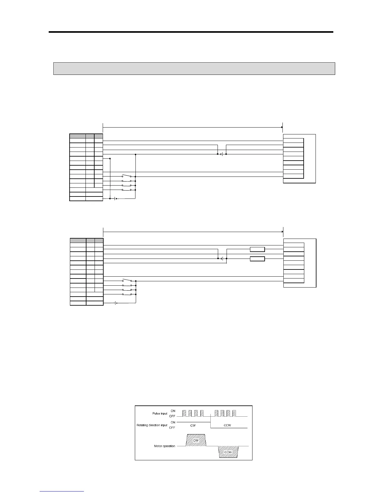
(1) Connection to a stepping motor driver (DC5V Power)
(2) Connection to a stepping motor driver (DC24V Power)
(Note1) In case of VEXTA PKD, timing output is on every time a motor rotates 7.2 degrees. For precise home return,
timing output and origin sensor should be structured by AND circuit. Depending on a system’s features, it is
recommended to use home return only by DOG signal or origin sensor by origin signal
rating is DC 24V).
(Note2) Connect resistors suitable for the driver in series if DC24V is used.
(Note3) Although origin, DOC, upper/lower limit signals are with fixed co
ntact, it may be used for general input if they
are not used. Emergency stop is available by the command (EMG).
(Note4) In case of XGB standard type, since only pulse + direction mode is available
, change input mode of stepping
motor driver to 1 phase input mode.
(Note 5) The above figure is example of XGB standard type. For high-
end type, Origin, DOG, upper/lower limit input
contact point is different with standard type.
DOG
P04 P06
P05 P07
Upper limit
P01 P03
Low limit
P00 P02
Signal Ch0 Ch1
Direction P22 P23
Common COM
DOG
P04 P06
P05 P07
High limit
P01 P03
Low limit P00 P02