Appendix 3 Motor Wiring Example
App.3 - 7
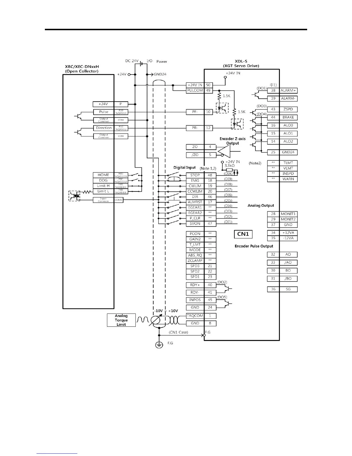
(b) In case of XBC/XEC-DN**H
※This picture is based on 1-axis. For more information about 2-axis wiring, refer to
pin information.
(Note1) Input Signal DI1~DIA, Output Signal DO1~DO5 is assigned initial signal from factory shipment
(Note2) ** Not assigned Signal. Allocation can be changed by setting servo parameter