EasyManua.ls Logo

LSIS XEC-DP64H User Manual

LSIS XEC-DP64H
315 pages
To Next Page IconTo Next Page
To Previous Page IconTo Previous Page
Page #83 background imageLoading...
Page #83 background image
Chapter 3 Before positioning
3- 46
3) Since the operation mode of step 3 is single, the next step is No. 4.
4) Step 4 has been set as end/repeat 1, it operates up to absolute coordinates 40,000 when step 4
operates by the second operation instruction, and stops without dwell time, and the next step
points at step 1 which has been designated as the Repeat step.
5) The operation pattern can be illustrated as follows.
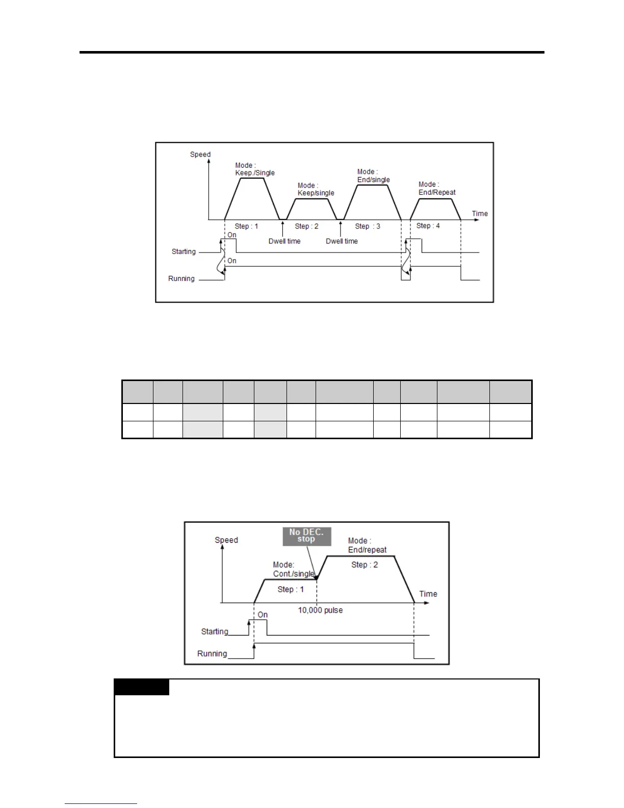
(d) Incessant Operation
Incessant operation refers to the operation that continues the steps set as continued operation by
the operation instruction.
• The continued operation can be explained with the operation data in the following table.
Step No.
Coordina
tes
Operation
pattern
Control
Operation
mode
Repeatin
g step
Target position
[Pulse]
M
code
Acc./Dec.
No.
Speed
[pls/s]
Dwell time
[]
1 INC Continuous Position Single 0 10,000 0 1 500 100
2 INC End Position Repeat 1 20,000 0 1 1,000 0
1) Since the operation pattern of step 1 has been set as continued, it operates up to the
incremental coordinates 10,000 pulse at 500pps by the first operation instruction, and changes
the operation speed to 1,000pps without deceleration or stop and continues to operate step 2.
2) Because the operation pattern of step 2 is end, it moves to incremental coordinates 20,000 and
the positioning ends after the dwell time.
Remark
• If the direction changes during the continued operation, error code 511 comes out and the
operation stops. If the direction has to change, change “Continuous” into “End” or “Keep”.

Table of Contents

Questions and Answers:

LSIS XEC-DP64H Specifications

General IconGeneral
BrandLSIS
ModelXEC-DP64H
CategoryController
LanguageEnglish

Summary

XGB Built-in Positioning

Safety Instruction

Crucial safety guidelines to be followed before operating the product.

Chapter 1 General

Provides general information about the positioning function, including purpose and features.

Chapter 2 General Specification

Provides general specifications for the XGB series, including environmental and immunity details.

Chapter 3 Before Positioning

Explains various positioning functions, parameters, and operation data.

Chapter 4 Positioning Check

Outlines the procedure for testing XGB positioning operation before use.

Chapter 5 Positioning Instructions

Provides detailed explanations for various positioning instructions like Origin Return, Direct Start, etc.

Chapter 6 Positioning Monitoring Package

Introduces the XGB positioning monitoring package for status monitoring and test operation.

Chapter 7 Program Examples of Positioning

Provides practical program examples for various positioning functions.

Chapter 8 Troubleshooting Procedure

Outlines basic steps for troubleshooting errors in XGB PLC and positioning functions.

Appendix 1 List of Error Codes

Details specific error codes related to the XGB positioning function.

Appendix 2 Positioning Instruction and K area List

Provides a list of dedicated K areas for positioning parameters and instructions.

Appendix 3 Motor Wiring Example

Illustrates wiring examples for connecting XGB PLC to servo motors.

Appendix 4 Dimension

Provides dimensional drawings for standard XGB main units (XBM-DN/DR series).

Related product manuals