Chapter 3 Before positioning
3- 45
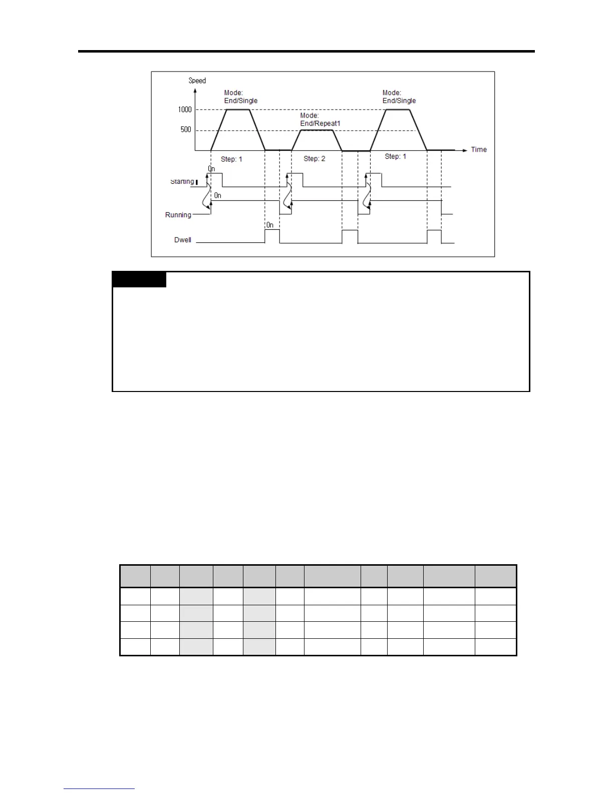
Remark
•If the operation mode is set as single, set the operating step number in the IST at 0, then the
step specified in the current step number (axis X: K426(%KW426), axis Y: K436 (%KW436))
in area K for positioning.
•If the operation mode is set as Repeat and the Repeat step is set at 0, the step stops operating
and the next step changes into 0.
In this case, the operating step gets out of the range of 1~30 (1~80 for the compact
standard/high-end type) and error code 512 comes out, so be careful of the repeating step
setting when you set at the repeating operation.
(c) Continued Operation
•Continued operation refers to the operation which carried out positioning to the target position by
using the data of the corresponding operating step by the operation instruction and continues the
next operating steps without any additional operation instructions with the positioning not completed
after the dwell time.
•The next operating steps differ according to the current operating mode of the steps.
A) The operation mode of the current step is single: current operating step + 1
B) The operation mode of the current step is repetition: the step designated as Repeat in the current
operation step
•If you use the continued operation pattern, you can conduct the pattern operation that sequentially
carried out multiple operating steps with only one operation instruction.
•The continued operation can be explained with the operation data in the following table.
Step No.
Coordina
tes
Operation
pattern
Control
Operation
mode
Repeatin
g step
Target position
[Pulse]
M
code
Acc./Dec.
No.
Speed
[pls/s]
Dwell time
[㎳]
1 Absolute Keep Position Single 0 10,000 0 0 1,000 100
2 Absolute Keep Position Single 0 20,000 0 0 500 100
3 Absolute End Position Single 0 30,000 0 1 1,000 0
4 Absolute End Position Repeat 1 40,000 0 1 500 0
1) Steps 1 and 2 are continued in the operation pattern and single in the operation mode, so they
operate at 1,000pps to the pulse of absolute coordinates 10,000 and then operates step 2, the
next step, without waiting for the next operation instruction when the dwell time passes. If the
dwell time passes after step 2, step 3 is operated.
2) Step 3, of which the operation pattern is end, operates up to absolute coordinates 30,000, and
then stops right away because the dwell time is 0, and the positioning completion bit turns on
for a scan.