12Y6181B
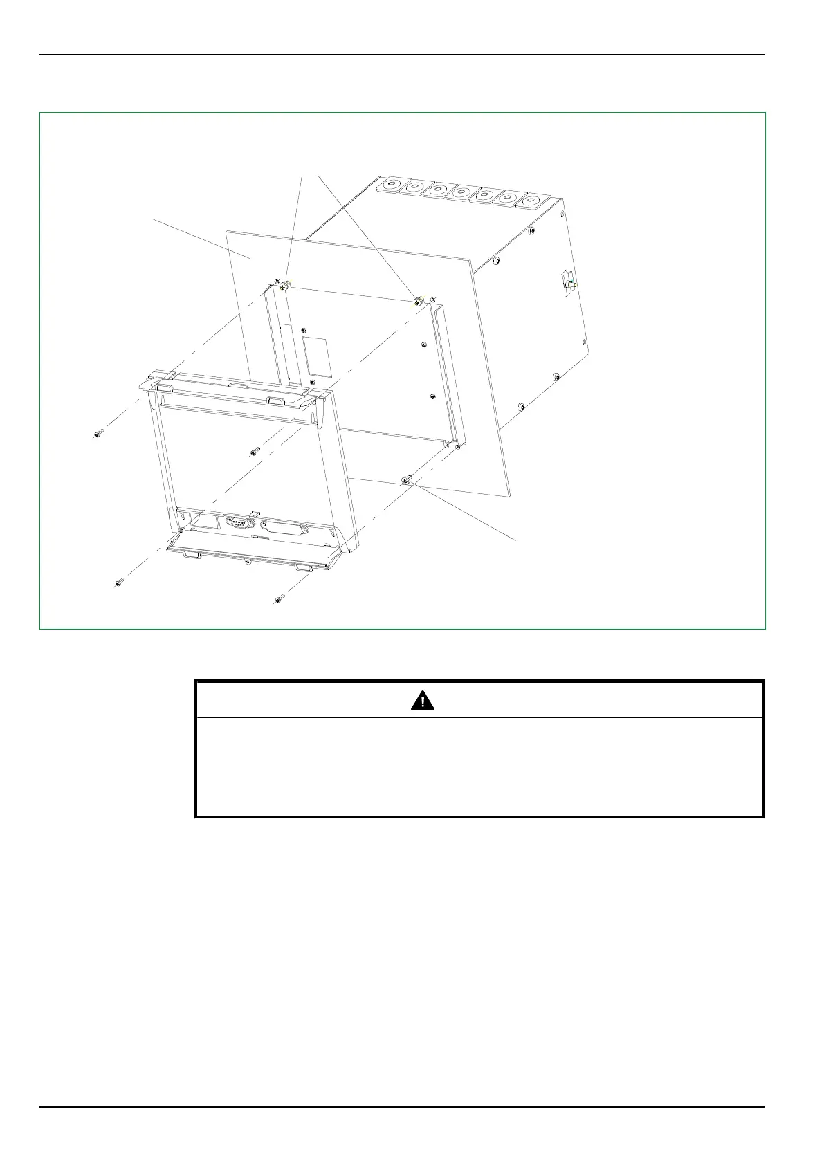
M4
< 3 mm
M3.5
Merely loosen the
upper screws and
hook device on side
plates to mount
For panels with a
thickness ≥ 2 mm,
replace the M3 bolts
with the enclosed
longer M3 bolts
Remove the lower
screws completely
prior to mounting
Fig. 5-3: Installation of a case into a control panel. Flush-mount method 1 (without the angle brackets and frame ).
Example for a device with a 40 TE case.
WARNING
The P634 has increased mechanical robustness if either the surface-mounted
case or for the flush-mounted case flush-mount method 2 (with angle
brackets and frame, see Fig. 5-5, (p. 5-9)) is used.
Connection of protective grounding conductor: See Section 5.5, (p. 5-12).
For flush-mount method 2 (using the angle brackets and frame), the procedure is
as follows:
1.
Remove the screws as shown in Fig. 5-4, (p. 5-9), ➀ and mount the
enclosed angle brackets using these same screws.
2.
Then push the device into the control panel cutout from the front.
3.
Secure the device to the control panel by using the enclosed M6 screws
(see Fig. 5-5, (p. 5-9)).
4.
Assemble the cover frame and snap-fasten onto the fixing screws.
P634
5 Installation and Connection
5-8 P634/EN M/R-42-A // P634‑311‑653