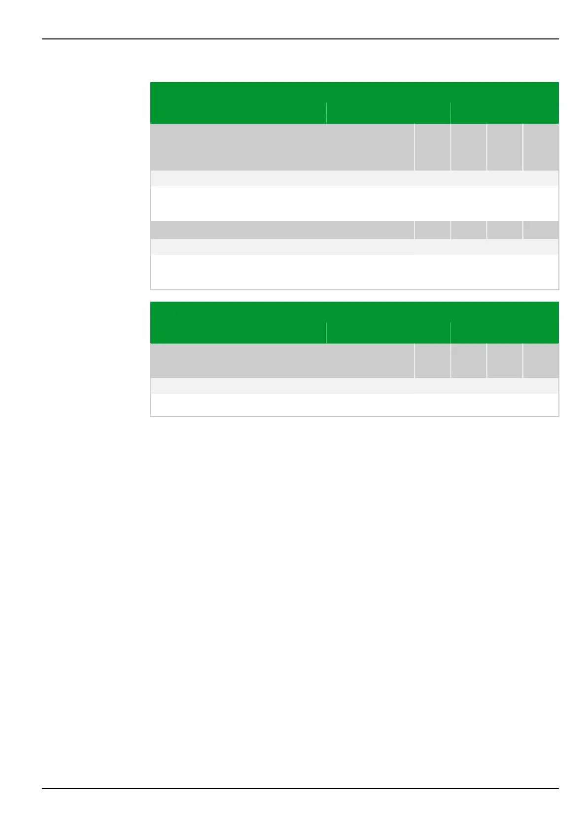
Parameter Address
Default Min Max Unit Logic Diagram
“Logical”
communication
interface 2
COMM2: Command block. USER
103 172
0: No Fig. 3-14, (p. 3-19)
[spacer]
When command blocking is activated, commands are rejected at communication
interface 2.
[spacer]
COMM2: Sig./meas.block.USER
103 076
0: No Fig. 3-14, (p. 3-19)
[spacer]
When signal and measured value blocking user is activated, no signals or
measured data are transmitted through communication interface COMM2.
Parameter Address
Default Min Max Unit Logic Diagram
Binary and analog
output
OUTP: Outp.rel.block USER
021 014
0: No Fig. 3-29, (p. 3-46)
[spacer]
When this blocking is activated, all output relays are blocked.
7 Settings P634
P634/EN M/R-42-A // P634‑311‑653 7-75