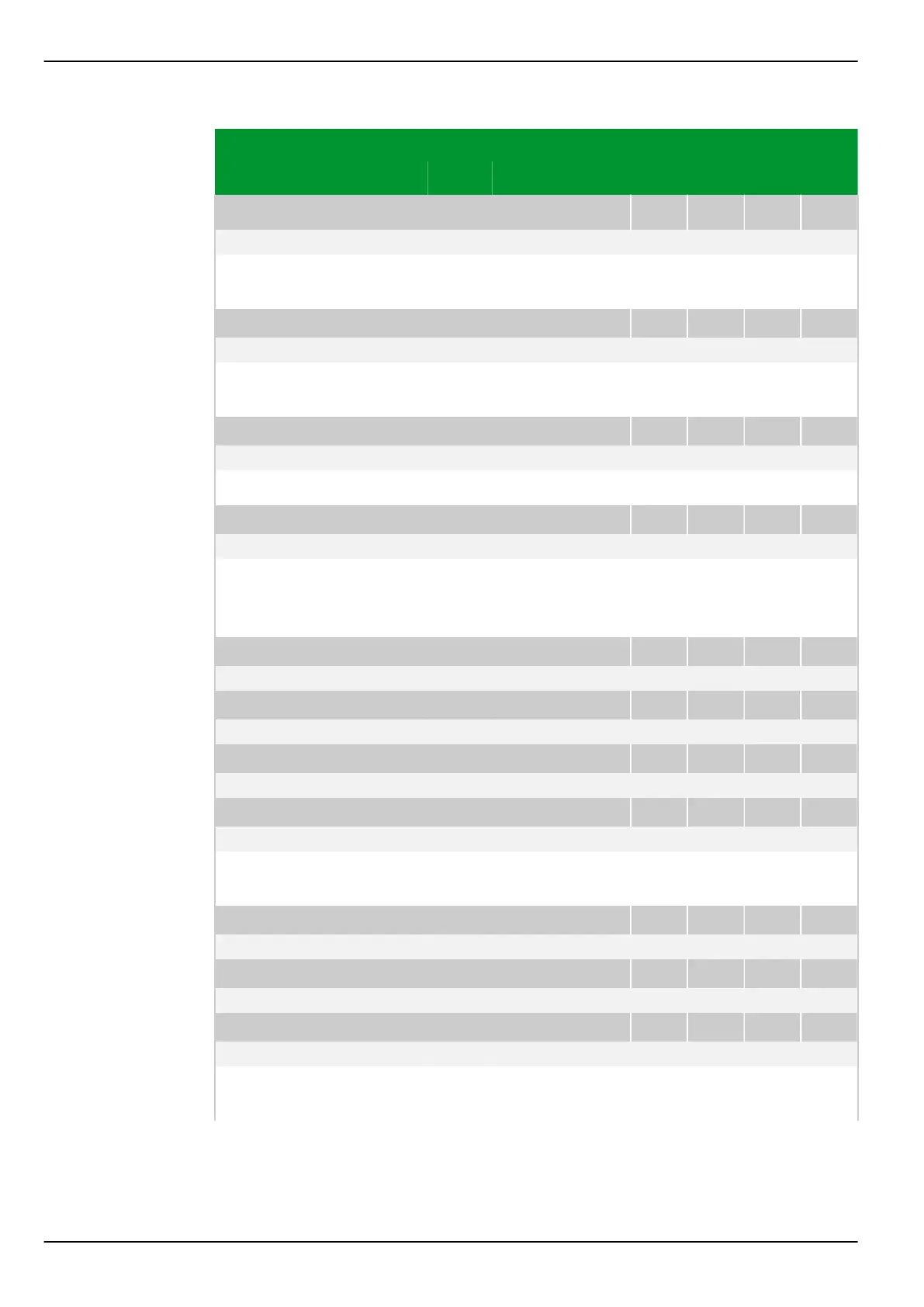
Parameter Address
Default Min Max Unit Logic Diagram
Main function
MAIN: Device on-line
003 030
0: No (= off) Fig. 3-55, (p. 3-87)
[spacer]
Switching the device off-line or on-line. Some parameters can only be changed
when protection is disabled.
[spacer]
MAIN: Test mode USER
003 012
0: No Fig. 3-68, (p. 3-99)
[spacer]
When the test mode user is activated, signals or measured data for PC and
communication interfaces are labeled 'test mode'.
[spacer]
MAIN: Nominal frequ. fnom
010 030
50: 50 Hz
[spacer]
Setting for the nominal frequency of the protected system.
[spacer]
MAIN: Phase sequence
010 049
1: A - B - C
[spacer]
Setting the phase sequence A-B-C or A-C-B.
(Alternative terminology: Setting for the rotary field's direction, either clockwise
or anticlockwise.)
[spacer]
MAIN: Inom C.T.prim.,end a
019 020
200 1 50000 A Fig. 3-46, (p. 3-78)
[spacer]
MAIN: Inom C.T.prim.,end b
019 021
200 1 50000 A
[spacer]
MAIN: Inom C.T.prim.,end c
019 022
200 1 50000 A
[spacer]
MAIN: Inom C.T.prim.,end d
019 026
200 1 50000 A
[spacer]
Setting for the primary nominal current of the main current transformer (phase
currents) of end a or b .
[spacer]
MAIN: Inom C.T.Yprim,end a
019 027
200 1 50000 A
[spacer]
MAIN: Inom C.T.Yprim,end b
019 028
200 1 50000 A
[spacer]
MAIN: Inom C.T.Yprim,end c
019 029
200 1 50000 A
[spacer]
Setting for the primary nominal current of the main current transformer at the
neutral-point-to-ground connection.
P634 7 Settings
7-76 P634/EN M/R-42-A // P634‑311‑653