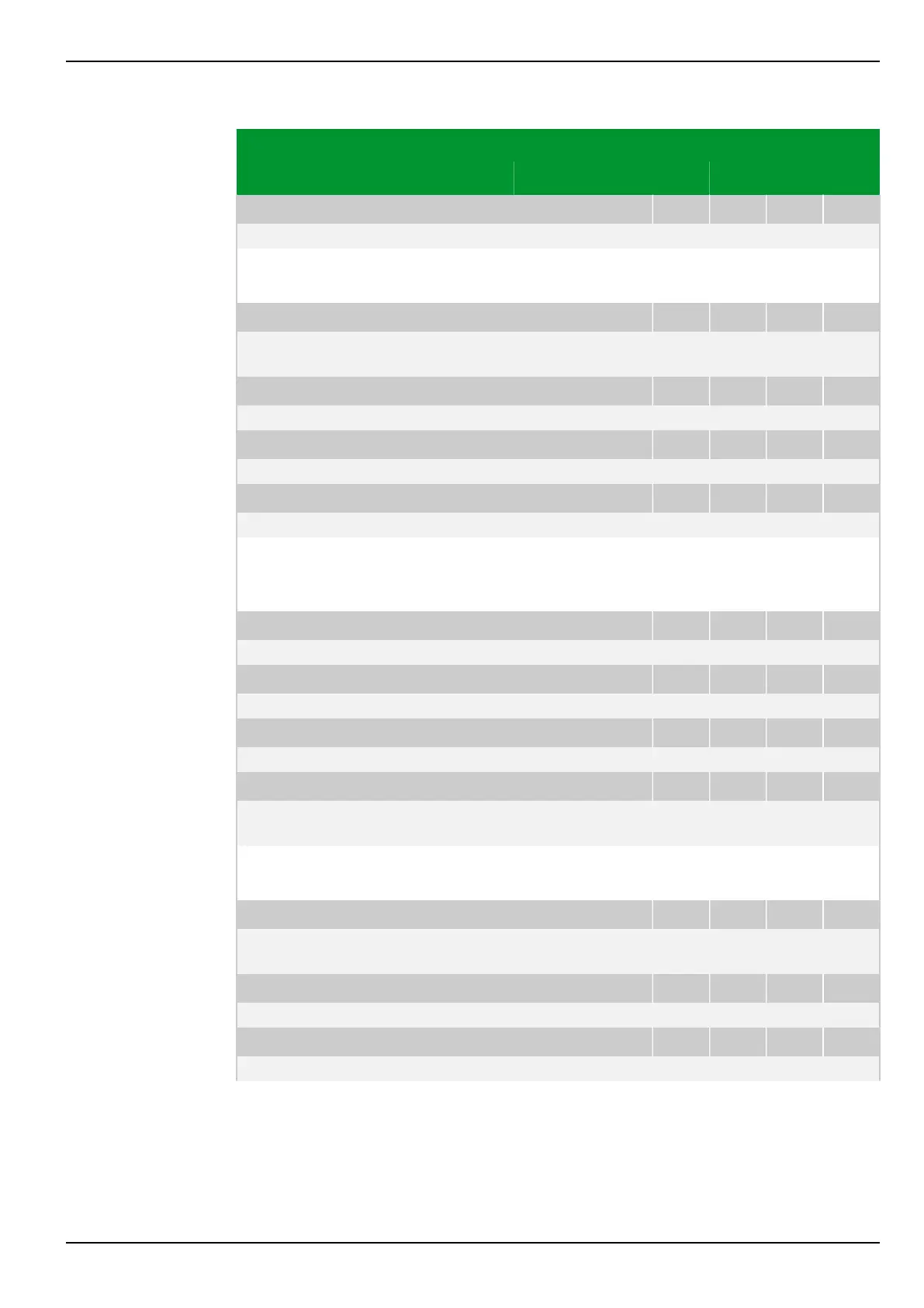
Parameter Address
Default Min Max Unit Logic Diagram
[spacer]
MAIN: Vnom V.T. prim.
010 002
100.0 0.1 1500.0 kV Fig. 3-50, (p. 3-82)
[spacer]
Setting for the primary nominal voltage of the system transformer for
measurement of phase-to-ground and phase-to-phase voltages.
[spacer]
MAIN: Inom device, end a
010 024
1.0: 1.0 A Fig. 3-39, (p. 3-64)
Fig. 3-40, (p. 3-65)
[spacer]
MAIN: Inom device, end b
010 025
1.0: 1.0 A Fig. 3-40, (p. 3-65)
[spacer]
MAIN: Inom device, end c
010 029
1.0: 1.0 A Fig. 3-40, (p. 3-65)
[spacer]
MAIN: Inom device, end d
010 047
1.0: 1.0 A Fig. 3-40, (p. 3-65)
[spacer]
Setting for the secondary nominal current of the system transformer for
measurement of phase currents of ends a, b, c and d. This also corresponds to
the nominal device current.
[spacer]
MAIN: IY,nom device, end a
010 142
1.0: 1.0 A Fig. 3-40, (p. 3-65)
[spacer]
MAIN: IY,nom device, end b
010 143
1.0: 1.0 A Fig. 3-40, (p. 3-65)
[spacer]
MAIN: IY,nom device, end c
010 144
1.0: 1.0 A Fig. 3-40, (p. 3-65)
[spacer]
MAIN: Vnom V.T. sec.
010 009
100 50 130 V Fig. 3-39, (p. 3-64)
Fig. 3-50, (p. 3-82)
[spacer]
Setting for the secondary nominal voltage of the system transformer for voltage
measurement.
[spacer]
MAIN: Conn.meas.circ. IP,a
010 140
1: Standard Fig. 3-39, (p. 3-64)
Fig. 3-40, (p. 3-65)
[spacer]
MAIN: Conn.meas.circ. IP,b
010 150
1: Standard Fig. 3-40, (p. 3-65)
[spacer]
MAIN: Conn.meas.circ. IP,c
010 160
1: Standard Fig. 3-40, (p. 3-65)
7 Settings P634
P634/EN M/R-42-A // P634‑311‑653 7-77