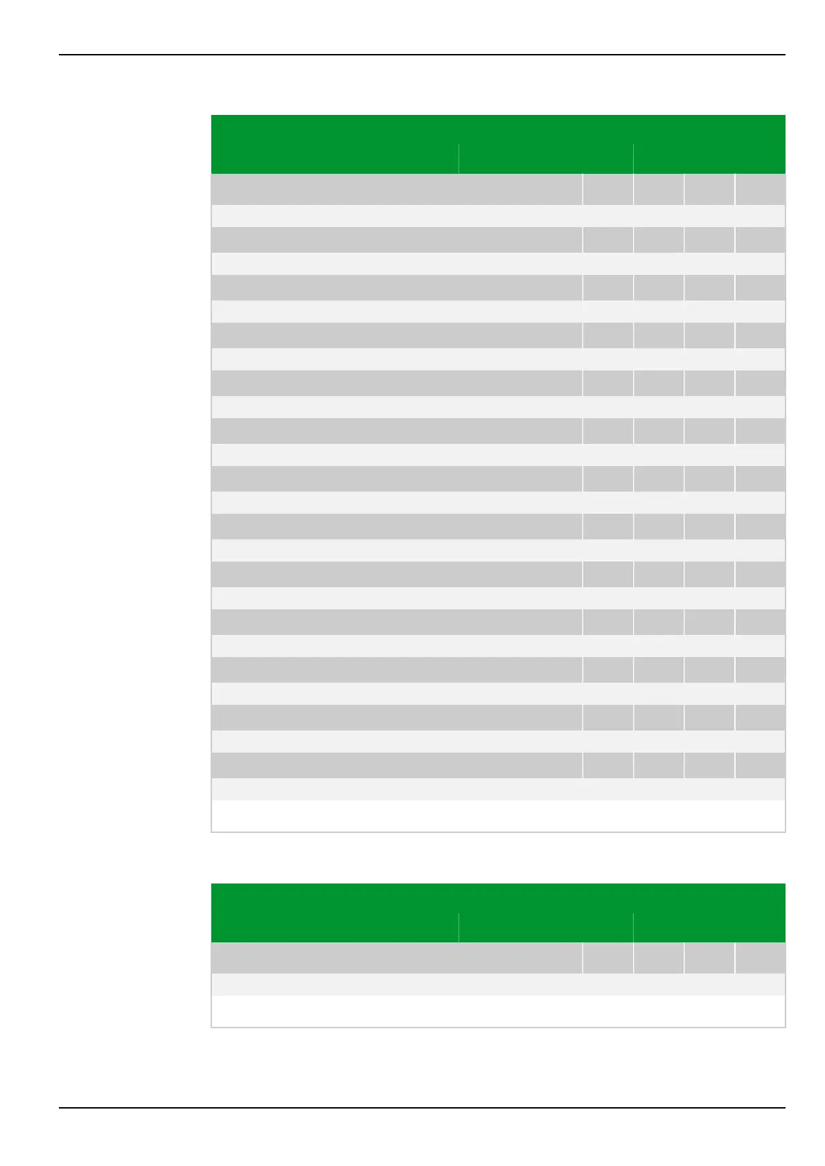
Parameter Address
Default Min Max Unit Logic Diagram
Binary counts
COUNT: Set counter 1 EXT
217 130
0: No
[spacer]
COUNT: Set counter 2 EXT
217 085
0: No
[spacer]
COUNT: Set counter 3 EXT
217 086
0: No
[spacer]
COUNT: Set counter 4 EXT
217 087
0: No
[spacer]
COUNT: Transmit counts EXT
217 009
0: No
[spacer]
COUNT: Reset EXT
217 004
0: No
[spacer]
COUNT: Enabled
217 001
0: No Fig. 3-184, (p. 3-228)
[spacer]
COUNT: Transmit counts
217 010
0: No Fig. 3-184, (p. 3-228)
[spacer]
COUNT: Reset
217 005
0: No Fig. 3-184, (p. 3-228)
[spacer]
COUNT: Warning count 1
217 191
0: No
[spacer]
COUNT: Warning count 2
217 192
0: No
[spacer]
COUNT: Warning count 3
217 193
0: No
[spacer]
COUNT: Warning count 4
217 194
0: No
[spacer]
Warning that the counter value has exceeded the set limit value.
8.1.2 Control and Testing
Parameter Address
Default Min Max Unit Logic Diagram
Local control panel
LOC: Param. change enabl.
003 010
0: No
[spacer]
Setting the enable for changing values from the local control panel.
8 Information and Control Functions P634
P634/EN M/R-42-A // P634‑311‑653 8-151