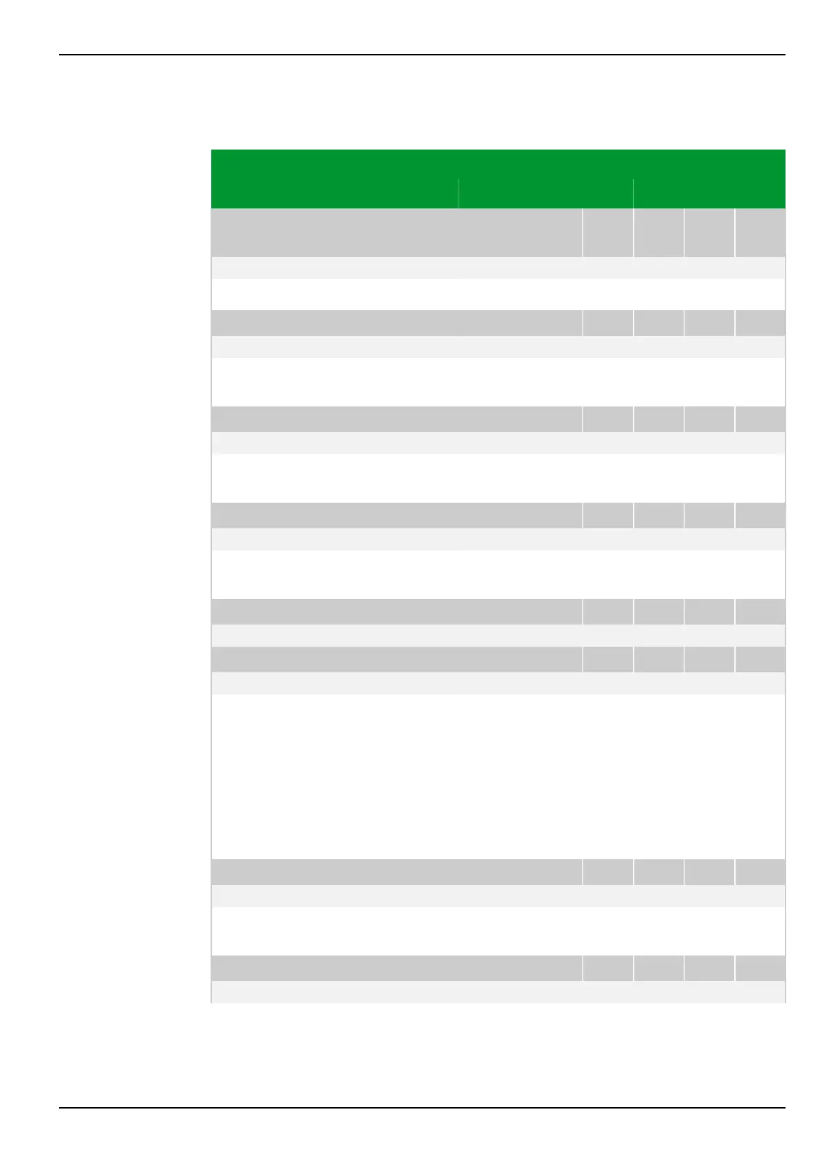
8.2.2 Measured Event Data
Parameter Address
Default Min Max Unit Logic Diagram
Overload data
acquisition
OL_DA: Overload duration
004 102
Not measured 0.0 6500.0 s Fig. 3-73, (p. 3-107)
[spacer]
Duration of the overload event.
[spacer]
OL_DA: Status THRM1 replica
004 155
Not measured 0 250 % Fig. 3-74, (p. 3-108)
[spacer]
Display of the buffer content of the thermal overload protection function THRM1
or THRM2, respectively.
[spacer]
OL_DA: Load current THRM1
004 159
Not measured 0.00 3.00 Inom Fig. 3-74, (p. 3-108)
[spacer]
Display of the load current used by the thermal overload protection function to
calculate the tripping time.
[spacer]
OL_DA: Object temp. THRM1
004 156
Not measured -40 300 °C Fig. 3-74, (p. 3-108)
[spacer]
Display of the temperature of the protected object as determined by function
THRM1 or THRM2, respectively.
[spacer]
OL_DA: Coolant temp.THRM1
004 157
Not measured -40 215 °C Fig. 3-74, (p. 3-108)
[spacer]
OL_DA: Coolant temp.THRM2
004 187
Not measured -40 215 °C
[spacer]
Display of the coolant temperature of the protected object. Depending on the
setting at THRM1: Select CTA PSx or THRM2: Select CTA PSx for
coolant temperature acquisition, one of the following values will be displayed:
●
Setting Default temp. value: Display of the set temperature value.
●
Setting From PT100: Display of the temperature measured by the
resistance thermometer.
●
Setting From 20 mA input: Display of the temperature measured via the
20 mA input.
[spacer]
OL_DA: Pre-trip t.leftTHRM1
004 158
Not measured 0.0 1000.0 min Fig. 3-74, (p. 3-108)
[spacer]
Display of the time remaining before the thermal overload protection function
THRM1 or THRM2, respectively, will reach the tripping threshold.
[spacer]
OL_DA: Offset THRM1 replica
004 191
Not measured -25000 25000 % Fig. 3-74, (p. 3-108)
8 Information and Control Functions P634
P634/EN M/R-42-A // P634‑311‑653 8-163