PCWS 2015 Setup Guide - 2nd Edition 3-49
What’s Inside?
Reassembling the PCWS 2015
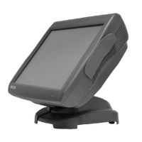
2. If an optional finger print reader or other device is installed in the top
cover, make sure the cable enters on the right or left to avoid interference
with the LCD/Touchscreen Assembly as shown in Figure 3-43. The option
cable can be attached to J29.
Figure 3-43: Top Cover Option Cable Routing
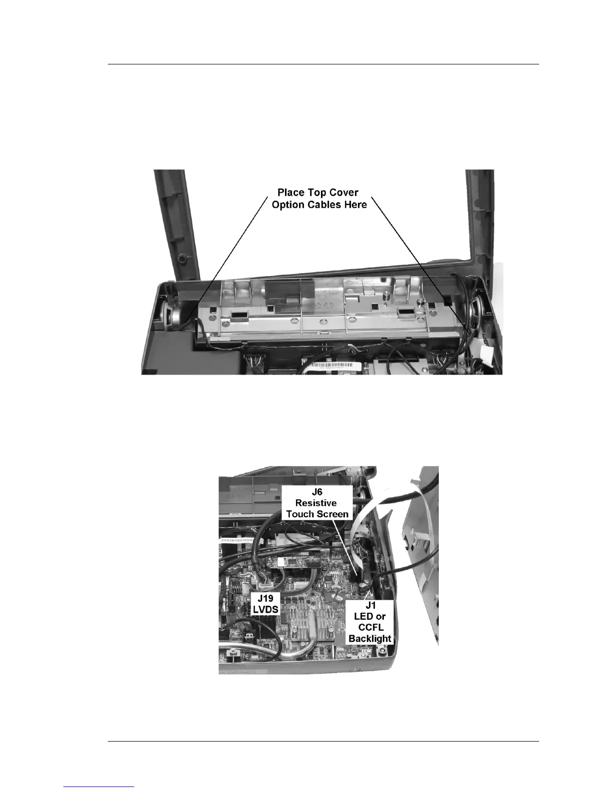
3. Place the LCD/Touchscreen Assembly to the right of the base and connect
the interface cables as shown in Figure 3-44.
Figure 3-44: Installing the LCD/Touchscreen Cables