3-50 PCWS 2015 Setup Guide - 2nd Edition
What’s Inside?
Reassembling the PCWS 2015
o LVDS Cable to J19. See page 3-30 (Resistive) and 3-31 (Capacitive)
for more information about changes to this cable.
o LED Backlight Cable to J1.
o Resistive Touchscreen connector to J6.
If a capacitive touchscreen is installed, connect the interface cable
to J2. J6 is not used.
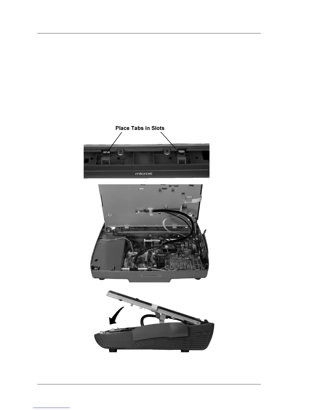
4. Install the LCD/Touchscreen Assembly in the base. The top of Figure 3-45,
below shows the tabs at the rear of the assembly and the slots in the base.
Insert the tabs into the base.
Figure 3-45: Installing the LCD/Touchscreen Assembly