13
MULTIPLE CPU SYSTEM CONCEPT
13.1 Mounting Position of CPU Module
13 - 4
9
UTILITY OPERATION
10
FUNCTIONS AND
PROGRAMMING
11
OVERVIEW OF
MULTIPLE CPU
SYSTEM
12
MULTIPLE CPU
SYSTEM
CONFIGURATION
13
MULTIPLE CPU
SYSTEM
CONCEPT
14
COMMUNICATIONS
BETWEEN CPU
MODULES
15
PARAMETERS
ADDED FOR
MULTIPLE CPU
16
PRECAUTIONS FOR
USE OF AnS SERIES
MODULE
(2) When CPU No. 1 is Basic model QCPU
The mounting position of each CPU module is shown in Table13.3.
(a) Mounting position of Basic model QCPU
Only one Basic model QCPU can be mounted on the CPU slot (slot on the right-
hand side of the power supply module) of the main base unit.
(b) Mounting position of Motion CPU
Only one Motion CPU can be mounted to slot 0 on the right of the Basic model
QCPU.
It cannot be mounted to other than slot 0.
(c) Mounting position of C Controller module
Only one C Controller module can be mounted at the right end of CPU modules.
No CPU can be mounted on the right side of the C Controller module.
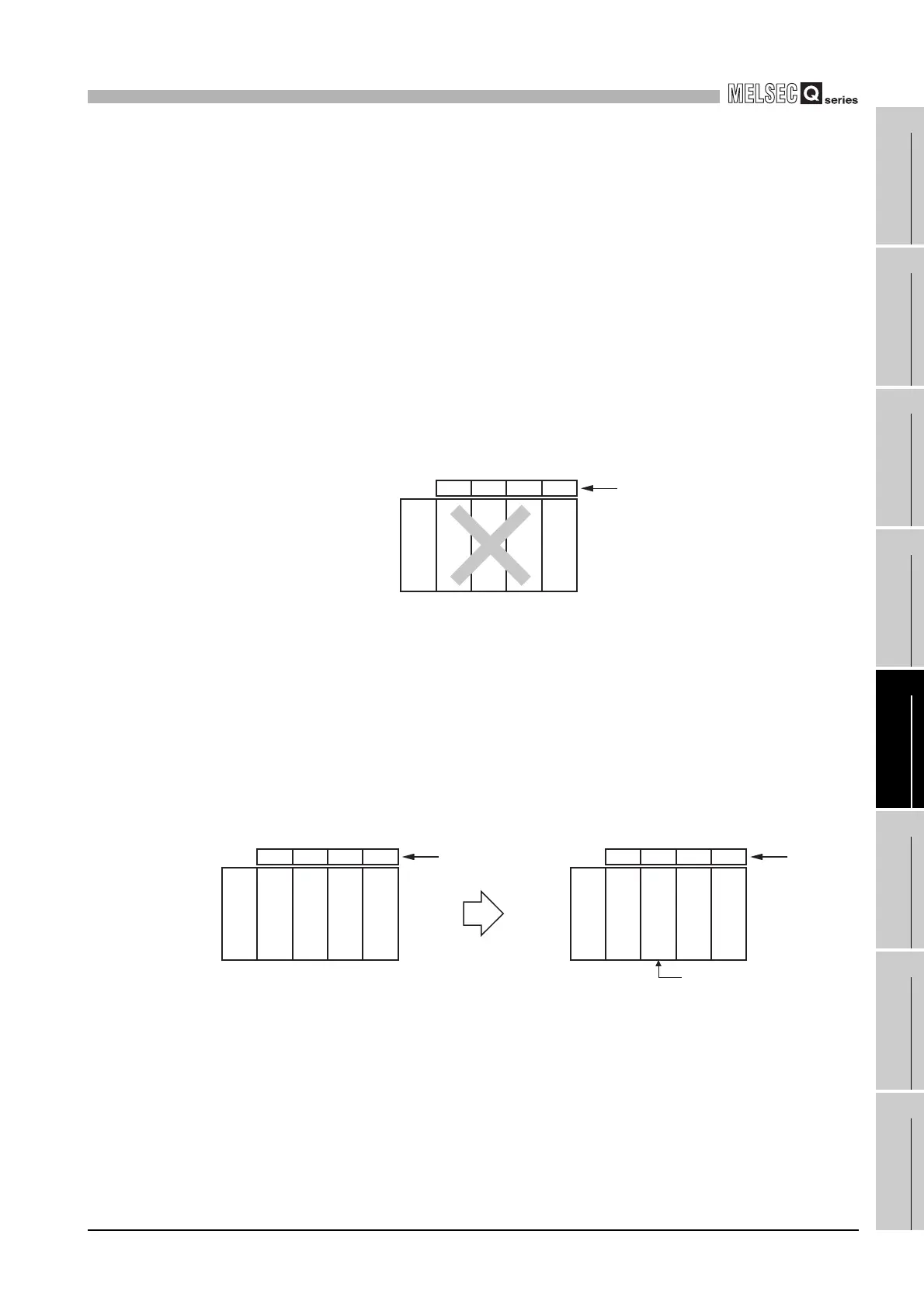
(d) "CPU (Empty)" setting
An empty slot can be reserved for future addition of a CPU module.
Set the number of CPU modules, including the one on the empty slot, in "No. of
CPU" on the <<Multiple CPU setting>> tab of the C Controller setting utility.
After that, set "CPU (Empty)" for the empty slot type in on the <<I/O assignment
setting>> tab of the C Controller setting utility.
1) When adding the Motion CPU in the future.
Set slot 0 as "CPU (Empty)."
Figure 13.3 Positions not allowed for C Controller module
Figure 13.4 "CPU (Empty)" setting for addition of Motion CPU
CPU 0 1 2
Power supply
module
Slot numbe
C Controller
module
Motion CPU
Basic model
QCPU
CPU 0 1 2 CPU 0 1 2
Added Motion CPU
Slot number Slot numbe
Power supply
module
Motion CPU
CPU (Empty)
Power supply
module
Basic model
QCPU
Basic model
QCPU

 Loading...


