PN: L-MAM2-E-201
Moog Casella DM2020 Installation and Startup Guide
3.2.7 Line Inductors
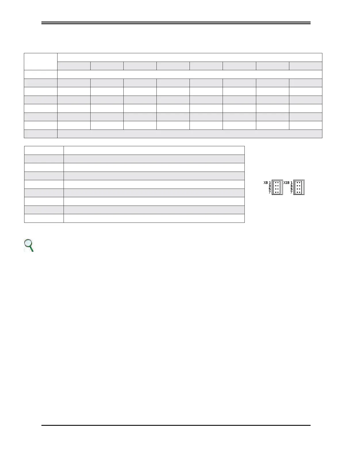
Connector X5 (X15), programmable interface
MODE FUNCTION
0 RS232 with 2 digital inputs
1 RS232 with 1 digital input and 1 digital output
2 The simulated encoder
3 EtherCAT network synchronisms monitor
4 3 digital inputs
5 3 digital outputs
6 1 digital input and 2 digital outputs
7 2 digital inputs and 1 digital output
No. of pins
CONFIGURATION MODE
0 1 2 3 4 5 6 7
1 +24 Volt output
2 INP A + OUT A + A+ SYNC 0 + INP A + OUT A + INP A + OUT A +
3 INP A - OUT A - A- SYNC 0 - INP A - OUT A - INP A - OUT A -
4 INP B+ INP B+ B+ SYNC 1 + INP B+ OUT B+ OUT B+ INP B+
5 INP B - INP B - B- SYNC 1 - INP B - OUT B - OUT B - INP B -
6 RX RX C + SM 2 + INP C + OUT C + OUT C + INP C +
7 TX TX C - SM 2 - INP C - OUT C - OUT C INP C -
8 0 Volt
INFORMATION
The maximum current that can be drawn from PIN 1 (output +24 V) is 200 mA
If you need more details or clarifications on motor/drive connections, please contact Moog assistance.
 Loading...
